一、引言
上期咱分享了环境搭建与GPIO点灯实验,今儿在此基础上,验证一下驱动8x8的LED点阵屏,由于之前的环境与VisionFive.gpio包已安装好,因此实验起来比较顺利。由参考的脚本可知,实验中需用到一个按键开关作为中断触发LED点阵屏显示。
二、硬件连接
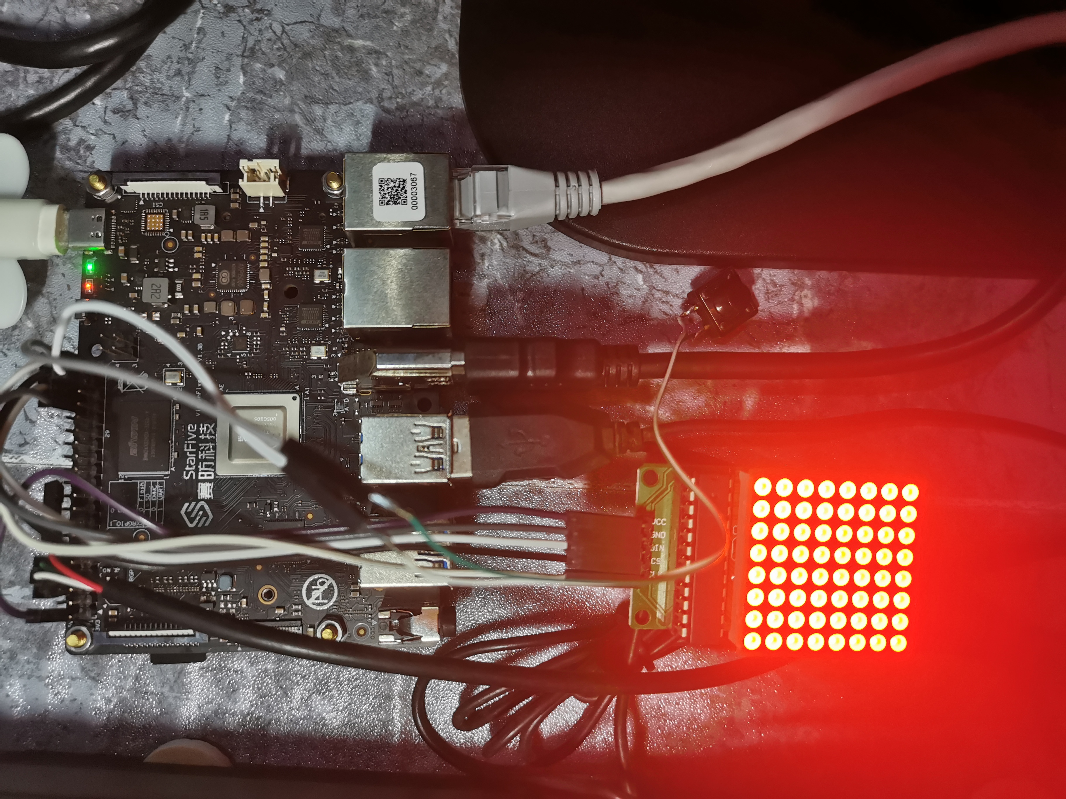
上图为硬件实物连接情况,初始上电状态为全亮LED点阵屏。
咱连接点阵屏与按键模块,是通过连接板上40-Pin Header。

MAX7219串行点阵显示模块与板上40-Pin Header连接关系:

按键开关一端连接一个信号输入GPIO口,设定为低电平有效;另一端连接GND。

三、脚本修改
在官方提供的参考脚本上,扩展显示其它内容。
命令执行流程:
开发板上电后,串口输出显示待登录状态,说明网络已初始化完成,因此可使用PuTTY登录到开发板上。然后将普通用户变更为超级用户,然后进入到sample-code目录下,由于官方提供的参考脚本文件为只读属性,因此使用vim编辑是无效的,需要使用chmod命令将文件属性更新为可读可写。这样接下来可以使用vim编辑该脚本文件。命令执行步骤如下图所示:

edge_detection_with_LED_Matrix.py代码完善如下:
"""
Step 1:
Please make sure the LED Dot Matrix is connected to the correct pins.
The following table describes how to connect LED Dot Matrix to the 40-pin header.
-----------------------------------------
___MAX7219_______Pin Number_____Pin Name
VCC 2 5V Power
GND 34 GND
DIN 40 GPIO44
CS 38 GPIO61
CLK 36 GPIO36
Step 2:
Please make sure the button is connected to the correct pins.
The following table describes how to connect the button to the 40-pin header.
----------------------------------------
_______button____Pin Number_____Pin Name
one end 37 GPIO60
The other end 39 GND
-----------------------------------------
"""
import VisionFive.gpio as GPIO
import sys
import time
DIN = 40
CS = 38
CLK = 36
buffer = [
"01111000",
"01000000",
"01111000",
"01001111",
"01111001",
"00001111",
"00000001",
"00001111",
]
buffer_13 = [
"00001000",
"00001000",
"01111111",
"01001001",
"01001001",
"01111111",
"00001000",
"00001000",
]
buffer_12 = [
"11111111",
"10111101",
"10010001",
"10111101",
"10010101",
"10111101",
"10000001",
"11111111",
]
buffer_11 = [
"01111110",
"00100000",
"00100000",
"00111110",
"01000010",
"10000100",
"00010100",
"00001000",
]
buffer_10 = [
"01001001",
"01111111",
"00001000",
"00011111",
"00100010",
"01011010",
"00000100",
"00001000",
]
buffer_9 = [
"00111110",
"00100010",
"00100010",
"00111110",
"00000010",
"00000010",
"00000010",
"00111110",
]
buffer_8 = [
"00111110",
"00100010",
"00100010",
"00111110",
"00100010",
"00100010",
"00100010",
"00111110",
]
buffer_7 = [
"00111110",
"00000010",
"00000010",
"00000100",
"00000100",
"00000100",
"00001000",
"00001000",
]
buffer_6 = [
"00111110",
"00100000",
"00100000",
"00111110",
"00100010",
"00100010",
"00100010",
"00111110",
]
buffer_5 = [
"00011110",
"00010000",
"00010000",
"00011110",
"00000010",
"00000010",
"00000010",
"00011110",
]
buffer_4 = [
"00000100",
"00001000",
"00010000",
"00100100",
"01000100",
"01111111",
"00000100",
"00000100",
]
buffer_3 = [
"00011100",
"00100010",
"00000010",
"00011110",
"00000010",
"00100010",
"00011100",
"00000000",
]
buffer_2 = [
"00011100",
"00100010",
"00000010",
"00000100",
"00001000",
"00010000",
"00111110",
"00000000",
]
buffer_1 = [
"00001000",
"00011000",
"00001000",
"00001000",
"00001000",
"00001000",
"00001000",
"00011100",
]
buffer_off = ["0", "0", "0", "0", "0", "0", "0", "0"]
key_pin = 37
def sendbyte(bytedata):
for bit in range(0, 8):
if (bytedata << bit) & 0x80:
GPIO.output(DIN, GPIO.HIGH)
else:
GPIO.output(DIN, GPIO.LOW)
GPIO.output(CLK, GPIO.HIGH)
GPIO.output(CLK, GPIO.LOW)
def WriteToReg(regaddr, bytedata):
GPIO.output(CS, GPIO.HIGH)
GPIO.output(CS, GPIO.LOW)
GPIO.output(CLK, GPIO.LOW)
sendbyte(regaddr)
sendbyte(bytedata)
GPIO.output(CS, GPIO.HIGH)
def disp_clean():
time.sleep(0.1)
for i in range(0, 8):
WriteToReg(i + 1, int(buffer_off[i], 2))
time.sleep(1)
def disp_numeral_13_to_1():
for id in range(13, 0, -1):
buffer_name = "buffer_{}".format(id)
list_buffer = eval(buffer_name)
for j in range(0, 8):
WriteToReg(j + 1, int(list_buffer[j], 2))
time.sleep(1)
for j in range(0, 8):
WriteToReg(j + 1, int(buffer_off[j], 2))
time.sleep(0.1)
def flash_logo():
for loop in range(0, 5):
for j in range(0, 8):
WriteToReg(j + 1, int(buffer_off[j], 2))
time.sleep(0.1)
for j in range(0, 8):
WriteToReg(j + 1, int(buffer[j], 2))
time.sleep(0.1)
def WriteALLReg():
disp_clean()
disp_numeral_13_to_1()
flash_logo()
def initData():
WriteToReg(0x09, 0x00)
WriteToReg(0x0A, 0x03)
WriteToReg(0x0B, 0x07)
WriteToReg(0x0C, 0x01)
WriteToReg(0x0F, 0x00)
def detect(pin, edge_type):
if edge_type == 1:
et = "Rising"
else:
et = "Falling"
if GPIO.getmode() == GPIO.BOARD:
print("{} edge was detected on pin:{}".format(et, pin))
else:
print("{} edge was detected on GPIO:{}".format(et, pin))
WriteALLReg()
global flag
flag = 1
def main():
global flag
flag = 0
GPIO.setmode(GPIO.BOARD)
GPIO.setup(DIN, GPIO.OUT)
GPIO.setup(CS, GPIO.OUT)
GPIO.setup(CLK, GPIO.OUT)
GPIO.setup(key_pin, GPIO.IN)
GPIO.add_event_detect(key_pin, GPIO.FALLING, callback=detect, bouncetime=2)
initData()
print("*------------------------------------------------------*")
print("Please press the key on pin {} to launch !!!".format(key_pin))
while True:
if flag == 1:
disp_clean()
GPIO.cleanup()
break
print("Exit demo.")
if __name__ == "__main__":
sys.exit(main())
当然开发者也可以使用FileZilla拷贝工具,通过ssh来传递python脚本文件,但没有vim来的高效。

使用vim编写完,保存退出后,运行“python3 edge_detection_with_LED_Matrix.py”命令即可验证效果。
四、显示效果
开机后,第一次运行脚本程序,如顶部视频所示,由全屏点亮,通过按一下开关,触发点阵屏显示。显示内容有“中国万岁”,“9”~“1”数字倒计显示,接着闪烁显示赛防科技的logo后熄灭点阵屏。再次运行脚本程序,如底部视频所示,按键后可再次触发。
五、终端命令关机
昉·星光 2开机后,说实话CPU处的温度还是有点高的,用手指触碰感觉很烫手,后期会考虑添上一个16mm x 16mm的散热片。在终端中,root模式下运行shutdown指令,在没有连接串口调试工具前提下,可做到完全关断电源,体验不错。

 /9
/9 


 工商网监
湘ICP备2023018690号
工商网监
湘ICP备2023018690号


 1112
1112

 淘帖
淘帖


