承接上期的呼吸灯效贴,今天来分享一下,将开发板做为BLE从机,手机做为BLE主机,在手机端的蓝牙调试助手发送指定字符去控制板上的LED0、LED1。
基于SDK中提供的从机“Peripheral”例程,手机端应用市场安装好“BLE调试助手”app。编译“Peripheral”例程后,使用“WCHISPStudio”下载编译后的“Peripheral.hex”文件。然后打开手机端的蓝牙与GPS开关,打开“BLE调试助手”app,扫描连接“Simple Peripheral”设备。连接该设备后则可看到“Generic Access”、“Generic Attribute”、“设备信息”和“Unknown Service”所有服务项。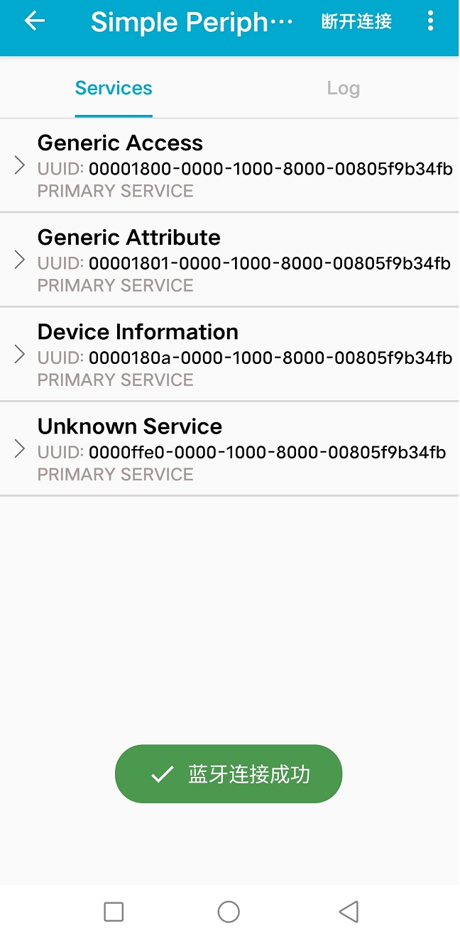
其中的Unknown Service服务是我们所需着重关注的,该服务是程序中自定义的一个通讯服务,UUID为0xFFE0,点击该条目,界面显示出0xFFE0服务下所有的characteristic,其包括“0xFFE1”、“0xFFE2”、“0xFFE3”、“0xFFE4”和“0xFFE5”,并显示出该服务的Properties。具体如下图所示:
根据图示可知,我们可通过“0xFFE1”,““0xFFE3”两个特征服务给开发进行写操作,也就是发送字符给开发板解析。然后回到例程中的“Peripheral_Init()”函数。
/*********************************************************************
 * @fn      Peripheral_Init
 *
 * [url=home.php?mod=space&uid=2666770]@Brief[/url]   Initialization function for the Peripheral App Task.
 *          This is called during initialization and should contain
 *          any application specific initialization (ie. hardware
 *          initialization/setup, table initialization, power up
 *          notificaiton ... ).
 *
 * [url=home.php?mod=space&uid=3142012]@param[/url]   task_id - the ID assigned by TMOS.  This ID should be
 *                    used to send messages and set timers.
 *
 * [url=home.php?mod=space&uid=1141835]@Return[/url]  none
 */
void Peripheral_Init()
{
    Peripheral_TaskID = TMOS_ProcessEventRegister(Peripheral_ProcessEvent);

    // Setup the GAP Peripheral Role Profile
    {
        uint8_t  initial_advertising_enable = TRUE;
        uint16_t desired_min_interval = DEFAULT_DESIRED_MIN_CONN_INTERVAL;
        uint16_t desired_max_interval = DEFAULT_DESIRED_MAX_CONN_INTERVAL;

        // Set the GAP Role Parameters
        GAPRole_SetParameter(GAPROLE_ADVERT_ENABLED, sizeof(uint8_t), &initial_advertising_enable);
        GAPRole_SetParameter(GAPROLE_SCAN_RSP_DATA, sizeof(scanRspData), scanRspData);
        GAPRole_SetParameter(GAPROLE_ADVERT_DATA, sizeof(advertData), advertData);
        GAPRole_SetParameter(GAPROLE_MIN_CONN_INTERVAL, sizeof(uint16_t), &desired_min_interval);
        GAPRole_SetParameter(GAPROLE_MAX_CONN_INTERVAL, sizeof(uint16_t), &desired_max_interval);
    }

    {
        uint16_t advInt = DEFAULT_ADVERTISING_INTERVAL;

        // Set advertising interval
        GAP_SetParamValue(TGAP_DISC_ADV_INT_MIN, advInt);
        GAP_SetParamValue(TGAP_DISC_ADV_INT_MAX, advInt);

        // Enable scan req notify
        GAP_SetParamValue(TGAP_ADV_SCAN_REQ_NOTIFY, ENABLE);
    }

    // Setup the GAP Bond Manager
    {
        uint32_t passkey = 0; // passkey "000000"
        uint8_t  pairMode = GAPBOND_PAIRING_MODE_WAIT_FOR_REQ;
        uint8_t  mitm = TRUE;
        uint8_t  bonding = TRUE;
        uint8_t  ioCap = GAPBOND_IO_CAP_DISPLAY_ONLY;
        GAPBondMgr_SetParameter(GAPBOND_PERI_DEFAULT_PASSCODE, sizeof(uint32_t), &passkey);
        GAPBondMgr_SetParameter(GAPBOND_PERI_PAIRING_MODE, sizeof(uint8_t), &pairMode);
        GAPBondMgr_SetParameter(GAPBOND_PERI_MITM_PROTECTION, sizeof(uint8_t), &mitm);
        GAPBondMgr_SetParameter(GAPBOND_PERI_IO_CAPABILITIES, sizeof(uint8_t), &ioCap);
        GAPBondMgr_SetParameter(GAPBOND_PERI_BONDING_ENABLED, sizeof(uint8_t), &bonding);
    }

    // Initialize GATT attributes
    GGS_AddService(GATT_ALL_SERVICES);           // GAP
    GATTServApp_AddService(GATT_ALL_SERVICES);   // GATT attributes
    DevInfo_AddService();                        // Device Information Service
    SimpleProfile_AddService(GATT_ALL_SERVICES); // Simple GATT Profile

    // Set the GAP Characteristics
    GGS_SetParameter(GGS_DEVICE_NAME_ATT, GAP_DEVICE_NAME_LEN, attDeviceName);

    // Setup the SimpleProfile Characteristic Values
    {
        uint8_t charValue1[SIMPLEPROFILE_CHAR1_LEN] = {1};
        uint8_t charValue2[SIMPLEPROFILE_CHAR2_LEN] = {2};
        uint8_t charValue3[SIMPLEPROFILE_CHAR3_LEN] = {3};
        uint8_t charValue4[SIMPLEPROFILE_CHAR4_LEN] = {4};
        uint8_t charValue5[SIMPLEPROFILE_CHAR5_LEN] = {1, 2, 3, 4, 5};

        SimpleProfile_SetParameter(SIMPLEPROFILE_CHAR1, SIMPLEPROFILE_CHAR1_LEN, charValue1);
        SimpleProfile_SetParameter(SIMPLEPROFILE_CHAR2, SIMPLEPROFILE_CHAR2_LEN, charValue2);
        SimpleProfile_SetParameter(SIMPLEPROFILE_CHAR3, SIMPLEPROFILE_CHAR3_LEN, charValue3);
        SimpleProfile_SetParameter(SIMPLEPROFILE_CHAR4, SIMPLEPROFILE_CHAR4_LEN, charValue4);
        SimpleProfile_SetParameter(SIMPLEPROFILE_CHAR5, SIMPLEPROFILE_CHAR5_LEN, charValue5);
    }

    // Init Connection Item
    peripheralInitConnItem(&peripheralConnList);

    // Register callback with SimpleGATTprofile
    SimpleProfile_RegisterAppCBs(&Peripheral_SimpleProfileCBs);

    // Register receive scan request callback
    GAPRole_BroadcasterSetCB(&Broadcaster_BroadcasterCBs);

    // Setup a delayed profile startup
    tmos_set_event(Peripheral_TaskID, SBP_START_DEVICE_EVT);
}
代码注释// Register callback with SimpleGATTprofile,即是初始化注册的特征值变化回调接口。
// Simple GATT Profile Callbacks
static simpleProfileCBs_t Peripheral_SimpleProfileCBs = {
    simpleProfileChangeCB // Characteristic value change callback
};
然后再根据实验需求,在“simpleProfileChangeCB()”函数中实现控制板上LED0,LED1的逻辑处理代码。
/*********************************************************************
 * @fn      simpleProfileChangeCB
 *
 * @brief   Callback from SimpleBLEProfile indicating a value change
 *
 * @param   paramID - parameter ID of the value that was changed.
 *          pValue - pointer to data that was changed
 *          len - length of data
 *
 * @return  none
 */
static void simpleProfileChangeCB(uint8_t paramID, uint8_t *pValue, uint16_t len)
{
    switch(paramID)
    {
        case SIMPLEPROFILE_CHAR1:
        {
            uint8_t newValue[SIMPLEPROFILE_CHAR1_LEN];
            tmos_memcpy(newValue, pValue, len);
            if(newValue[0])
            {
                if(newValue[0]== 0x30)
                {
                    GPIOA_SetBits(GPIO_Pin_0);  //关闭LED0
                }
                else if(newValue[0]==0x31)
                {
                    GPIOA_ResetBits(GPIO_Pin_0);    //打开LED0
                }
                else if(newValue[0]==0x32)
                {
                    GPIOA_SetBits(GPIO_Pin_1);  //关闭LED1
                }
                else if(newValue[0]==0x33)
                {
                    GPIOA_ResetBits(GPIO_Pin_1); //打开LED1
                }
            }
            PRINT("profile ChangeCB CHAR1.. \n");
            break;
        }

        case SIMPLEPROFILE_CHAR3:
        {
            uint8_t newValue[SIMPLEPROFILE_CHAR3_LEN];
            tmos_memcpy(newValue, pValue, len);
            PRINT("profile ChangeCB CHAR3..\n");
            break;
        }

        default:
            // should not reach here!
            break;
    }
}
实验在“0xFFE1”服务特征值下进行,因此添加逻辑代码在“SIMPLEPROFILE_CHAR1”,如果想在“0xFFE3”服务特征值下实验,则将逻辑代码添加到“SIMPLEPROFILE_CHAR3”下。
完成上述代码编写完后,当然记得在main函数中添加LED0、LED1的GPIO口初始化代码,默认关闭LED0、LED1。这里笔者LED0使用PA0,LED1使用PA1。main()函数中内容如下:
/*********************************************************************
 * @fn      main
 *
 * @brief   主函数
 *
 * @return  none
 */
int main(void)
{
#if(defined(DCDC_ENABLE)) && (DCDC_ENABLE == TRUE)
    PWR_DCDCCfg(ENABLE);
#endif
    HSECFG_Capacitance(HSECap_18p);
    SetSysClock(CLK_SOURCE_HSE_PLL_62_4MHz);
#if(defined(HAL_SLEEP)) && (HAL_SLEEP == TRUE)
    GPIOA_ModeCfg(GPIO_Pin_All, GPIO_ModeIN_PU);
    GPIOB_ModeCfg(GPIO_Pin_All, GPIO_ModeIN_PU);
#endif
#ifdef DEBUG
    GPIOA_SetBits(GPIO_Pin_14);
    GPIOPinRemap(ENABLE, RB_PIN_UART0);
    GPIOA_ModeCfg(GPIO_Pin_14, GPIO_ModeOut_PP_5mA);
    UART0_DefInit();
#endif
    PRINT("%s\n", VER_LIB);

    //LED 0
    GPIOA_ModeCfg( GPIO_Pin_0, GPIO_ModeOut_PP_5mA );
    //LED 1
    GPIOA_ModeCfg( GPIO_Pin_1, GPIO_ModeOut_PP_5mA );
    GPIOA_SetBits(GPIO_Pin_0);
    GPIOA_SetBits(GPIO_Pin_1);  //默认关闭LED0、LED1

    CH58x_BLEInit();
    HAL_Init();
    GAPRole_PeripheralInit();
    Peripheral_Init();
    Main_Circulation();
}
开发板的硬件实物连线如下:
工程编译、下载后,实验演示正如代码中一样。发送数字0或者16进制30则关闭LED0,发送数字1或者16进制31则打开LED0,发送数字2或者16进制32则关闭LED1,发送数字3或者16进制33则打开LED1,效果见底部视频。
更多回帖
 长按上方图片保存到相册
 复制链接
复制链接