一些额外的评论:
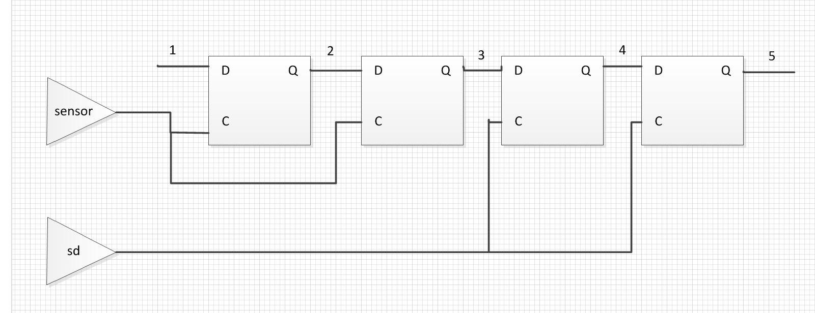
1)如果你的两个时钟不相关,即只要工具知道没有相位关系,那么你就不需要TIG,因为无论如何都不会分析路径3。
如果两个时钟可以追溯到FPGA的相同输入引脚,则工具只知道相位关系。
2)DATAPATHONLY意味着时钟路径被忽略,因此实际上“setup”或“hold”没有实际意义。
然而,将检查路径3的数据支持延迟,包括驱动触发器的Q时钟和接收触发器的输入设置时间。
在这种情况下使用FROM:TO约束可能很有用,例如,如果您有多个这样的数据路径并且想要约束它们,那么数据路径的延迟差异不能大于某个固定数量的时钟周期(通常是一个)。
再次没有分析延迟差异,但是它显然不能大于最大允许延迟,因为绝对路径延迟(不相对于时钟)不能小于零。
3)即使您有TIG约束,某些版本的工具仍会检查保持时间。
同样,这只适用于相关时钟。
如果您认为这些时钟是异步的,那么您最好使用FROM:TO ... DATAPATHONLY约束样式,因为它会阻止保持时间分析。
如果您真的不在乎数据路径中有多少延迟,您可以将延迟设置为大的延迟以防止设计过度约束。
- Gabor
以上来自于谷歌翻译
以下为原文
Some additional comments:
1) If your two clocks are not related, i.e. as far as the tools know there is no phase relationship, then you don't need the TIG because path 3 won't be analyzed anyway. The tools only know about the phase relationship if the two clocks can be traced back to the same input pin of the FPGA.
2) DATAPATHONLY means that the clock paths are ignored, so in effect there is no real meaning for "setup" or "hold." However the path 3 will be checked for data prop delay including the clock to Q of the driving flip-flop and the input setup time of the receiving flip-flop. Using a FROM : TO constraint in this instance may be useful if for example you have multiple such data paths and want to constrain them so that the data paths cannot have delay differences greater than some fixed number of clock cycles (usually one). Again the delay difference is not analyzed, but it obviously cannot be greater than the maximum allowed delay because the absolute path delay (not relative to clocks) cannot be less than zero.
3) Some versions of the tools will still check for hold timing even if you have a TIG constraint. Again this would only be for related clocks. If you consider these clocks to be asynchronous, then you're better off with the FROM : TO ... DATAPATHONLY style of constraint, since it will prevent hold time analysis. If you really don't care how much delay is in the data path you can set the delay to something large to prevent overconstraining the design.
-- Gabor

 举报
举报


 举报
举报

 举报
举报

 举报
举报

 举报
举报

