设备树修改如下:
project device/config/chips/d1-h/
[url=home.php?mod=space&uid=1999721]@@[/url] -6,7 +6,6 @@
/dts-v1/;
-/memreserve/ 0x42000000 0x100000; /* dsp used 1MB */
#include "sun20iw1p1.dtsi"
/{
@@ -15,7 +14,6 @@
aliases {
dsp0 = &dsp0;
dsp0_gpio_int= &dsp0_gpio_int;
- gmac0 = &gmac0;
};
dsp0: dsp0 {
@@ -31,7 +29,7 @@
reg_vdd_cpu: vdd-cpu {
compatible = "sunxi-pwm-regulator";
- pwms = <&pwm 0 5000 1>;
+ pwms = <&pwm 0 5000 0>;
regulator-name = "vdd_cpu";
regulator-min-microvolt = <810000>;
regulator-max-microvolt = <1160000>;
@@ -47,7 +45,15 @@
regulator-min-microvolt = <5000000>;
regulator-max-microvolt = <5000000>;
regulator-enable-ramp-delay = <1000>;
- gpio = <&pio PD 19 GPIO_ACTIVE_HIGH>;
+ enable-active-high;
+ };
+
+ reg_3v3: vdd_3v3 {
+ compatible = "regulator-fixed";
+ regulator-name = "vdd_3v3";
+ regulator-min-microvolt = <3300000>;
+ regulator-max-microvolt = <3300000>;
+ regulator-enable-ramp-delay = <1000>;
enable-active-high;
};
};
@@ -234,62 +240,42 @@
gmac_pins_a: gmac@0 {
pins = "PE0", "PE1", "PE2", "PE3",
- "PE4", "PE5", "PE6", "PE7",
- "PE8", "PE9", "PE10", "PE11",
- "PE12", "PE13", "PE14", "PE15";
+ "PE4", "PE5", "PE6", "PE7",
+ "PE8", "PE9";
function = "gmac0";
- muxsel = <8>; /* for uboot driver */
drive-strength = <10>;
};
gmac_pins_b: gmac@1 {
pins = "PE0", "PE1", "PE2", "PE3",
- "PE4", "PE5", "PE6", "PE7",
- "PE8", "PE9", "PE10", "PE11",
- "PE12", "PE13", "PE14", "PE15";
+ "PE4", "PE5", "PE6", "PE7",
+ "PE8", "PE9";
function = "gpio_in";
};
dmic_pins_a: dmic@0 {
/* DMIC_PIN: CLK, DATA0, DATA1, DATA2 */
- pins = "PE17", "PB11", "PB10", "PD17";
+ pins = "PE17", "PB11";
function = "dmic";
drive-strength = <20>;
bias-disable;
};
dmic_pins_b: dmic@1 {
- pins = "PE17", "PB11", "PB10", "PD17";
+ pins = "PE17", "PB11";
function = "io_disabled";
drive-strength = <20>;
bias-disable;
};
daudio0_pins_a: daudio0@0 {
- /* MCLK, BCLK, LRCK */
- pins = "PE17", "PE16", "PE15";
+ pins = "PE17", "PE16", "PE15", "PE14", "PE13";
function = "i2s0";
drive-strength = <20>;
bias-disable;
};
- daudio0_pins_b: daudio0@1 {
- /* DIN0 */
- pins = "PE14";
- function = "i2s0_din";
- drive-strength = <20>;
- bias-disable;
- };
-
- daudio0_pins_c: daudio0@2 {
- /* DOUT0 */
- pins = "PE13";
- function = "i2s0_dout";
- drive-strength = <20>;
- bias-disable;
- };
-
- daudio0_pins_d: daudio0_sleep@0 {
+ daudio0_pins_b: daudio0_sleep@0 {
pins = "PE17", "PE16", "PE15", "PE14", "PE13";
function = "io_disabled";
drive-strength = <20>;
@@ -297,30 +283,13 @@
};
daudio1_pins_a: daudio1@0 {
- /* MCLK, LRCK, BCLK */
- pins = "PG11", "PG12", "PG13";
+ pins = "PG11", "PG12", "PG13", "PG14", "PG15";
function = "i2s1";
drive-strength = <20>;
bias-disable;
};
- daudio1_pins_b: daudio1@1 {
- /* DIN0 */
- pins = "PG14";
- function = "i2s1_din";
- drive-strength = <20>;
- bias-disable;
- };
-
- daudio1_pins_c: daudio1@2 {
- /* DOUT0 */
- pins = "PG15";
- function = "i2s1_dout";
- drive-strength = <20>;
- bias-disable;
- };
-
- daudio1_pins_d: daudio1_sleep@0 {
+ daudio1_pins_b: daudio1_sleep@0 {
pins = "PG11", "PG12", "PG13", "PG14", "PG15";
function = "io_disabled";
drive-strength = <20>;
@@ -374,7 +343,7 @@
};
spi0_pins_a: spi0@0 {
- pins = "PC2", "PC4", "PC5"; /* clk, mosi, miso */
+ pins = "PC2", "PC4", "PC5","PC7", "PC6"; /*clk mosi miso hold wp*/
function = "spi0";
muxsel = <2>;
drive-strength = <10>;
@@ -385,7 +354,7 @@
function = "spi0";
muxsel = <2>;
drive-strength = <10>;
- bias-pull-up; /* cs, hold, wp should be pulled up */
+ bias-pull-up; /* only CS should be pulled up */
};
spi0_pins_c: spi0@2 {
@@ -396,16 +365,16 @@
};
spi1_pins_a: spi1@0 {
- pins = "PD11", "PD12", "PD13"; /* clk, mosi, miso */
+ pins = "PD11", "PD12", "PD13","PD14", "PD15"; /*clk mosi miso hold wp*/
function = "spi1";
drive-strength = <10>;
};
spi1_pins_b: spi1@1 {
- pins = "PD10", "PD14", "PD15";
+ pins = "PD10";
function = "spi1";
drive-strength = <10>;
- bias-pull-up; /* cs, hold, wp should be pulled up */
+ bias-pull-up; // only CS should be pulled up
};
spi1_pins_c: spi1@2 {
@@ -447,9 +416,9 @@
pwm2_pin_b: pwm2@1 {
pins = "PD18";
- function = "gpio_out";
+ function = "gpio_in";
};
-/*
+
pwm7_pin_a: pwm7@0 {
pins = "PD22";
function = "pwm7";
@@ -461,7 +430,6 @@
pins = "PD22";
function = "gpio_in";
};
-*/
s_cir0_pins_a: s_cir@0 {
pins = "PB12";
@@ -486,6 +454,45 @@
pins = "PB0";
function = "gpio_in";
};
+
+ rgb18_20_pins_a: rgb18_20@0 {
+ pins = "PD0", "PD1", "PD2", "PD3", "PD4", "PD5", \
+ "PD6", "PD7", "PD8", "PD9", "PD10", "PD11", \
+ "PD12", "PD13", "PD14", "PD15", "PD16", "PD17", \
+ "PD18", "PD19", "PD20", "PD21";
+ function = "lcd0";
+ drive-strength = <20>;
+ bias-disable;
+ };
+
+ rgb18_20_pins_b: rgb18_20@1 {
+ pins = "PD0", "PD1", "PD2", "PD3", "PD4", "PD5", \
+ "PD6", "PD7", "PD8", "PD9", "PD10", "PD11", \
+ "PD12", "PD13", "PD14", "PD15", "PD16", "PD17", \
+ "PD18", "PD19", "PD20", "PD21";
+ function = "io_disabled";
+ bias-disable;
+ };
+
+ rgb18_10_pins_a: rgb18_10@0 {
+ pins = "PD0", "PD1", "PD2", "PD3", "PD4", "PD5", \
+ "PD6", "PD7", "PD8", "PD9", "PD10", "PD11", \
+ "PD12", "PD13", "PD14", "PD15", "PD16", "PD17", \
+ "PD18", "PD19", "PD20", "PD21";
+ function = "lcd0";
+ drive-strength = <10>;
+ bias-disable;
+ };
+
+ rgb18_10_pins_b: rgb18_10@1 {
+ pins = "PD0", "PD1", "PD2", "PD3", "PD4", "PD5", \
+ "PD6", "PD7", "PD8", "PD9", "PD10", "PD11", \
+ "PD12", "PD13", "PD14", "PD15", "PD16", "PD17", \
+ "PD18", "PD19", "PD20", "PD21";
+ function = "io_disabled";
+ bias-disable;
+ };
+
};
&uart0 {
@@ -510,11 +517,11 @@
};
&uart3 {
- compatible = "allwinner,sun20iw1-dsp-uart";
+ /*compatible = "allwinner,sun20iw1-dsp-uart";*/
pinctrl-names = "default", "sleep";
pinctrl-0 = <&uart3_pins_a>;
pinctrl-1 = <&uart3_pins_a>;
- status = "okay";
+ status = "disabled";
};
&soc {
@@ -557,12 +564,12 @@
compatible = "allwinner,sunxi-rfkill";
chip_en;
power_en;
- pinctrl-0 = <&wlan_pins_a>;
- pinctrl-names = "default";
status = "okay";
wlan: wlan@0 {
compatible = "allwinner,sunxi-wlan";
+ pinctrl-0 = <&wlan_pins_a>;
+ pinctrl-names = "default";
clock-names = "32k-fanout1";
clocks = <&ccu CLK_FANOUT1_OUT>;
wlan_busnum = <0x1>;
@@ -578,6 +585,8 @@
bt: bt@0 {
compatible = "allwinner,sunxi-bt";
+ pinctrl-0 = <&wlan_pins_a>;
+ pinctrl-names = "default";
clock-names = "32k-fanout1";
clocks = <&ccu CLK_FANOUT1_OUT>;
/*bt_power_num = <0x01>;*/
@@ -590,13 +599,13 @@
};
};
- btlpm: btlpm@0 {
+ /*btlpm: btlpm@0 {
compatible = "allwinner,sunxi-btlpm";
uart_index = <0x1>;
bt_wake = <&pio PG 16 GPIO_ACTIVE_HIGH>;
bt_hostwake = <&pio PG 17 GPIO_ACTIVE_HIGH>;
status = "okay";
- };
+ };*/
addr_mgt: addr_mgt@0 {
compatible = "allwinner,sunxi-addr_mgt";
@@ -826,8 +835,8 @@ tvd_row*tvd_column is the total tvd channel number to be used in multichannel mo
pcm_lrck_period = <0x80>;
slot_width_select = <0x20>;
pinctrl-names = "default", "sleep";
- pinctrl-0 = <&daudio0_pins_a &daudio0_pins_b &daudio0_pins_c>;
- pinctrl-1 = <&daudio0_pins_d>;
+ pinctrl-0 = <&daudio0_pins_a>;
+ pinctrl-1 = <&daudio0_pins_b>;
pinctrl_used = <0x0>;
status = "disabled";
};
@@ -861,8 +870,8 @@ tvd_row*tvd_column is the total tvd channel number to be used in multichannel mo
pcm_lrck_period = <0x80>;
slot_width_select = <0x20>;
pinctrl-names = "default", "sleep";
- pinctrl-0 = <&daudio1_pins_a &daudio1_pins_b &daudio1_pins_c>;
- pinctrl-1 = <&daudio1_pins_d>;
+ pinctrl-0 = <&daudio1_pins_a>;
+ pinctrl-1 = <&daudio1_pins_b>;
pinctrl_used = <0x0>;
status = "disabled";
};
@@ -930,12 +939,10 @@ tvd_row*tvd_column is the total tvd channel number to be used in multichannel mo
*/
&usbc0 {
device_type = "usbc0";
- usb_port_type = <0x2>;
+ usb_port_type = <0x0>;
usb_detect_type = <0x1>;
usb_detect_mode = <0>;
- usb_id_gpio = <&pio PD 21 GPIO_ACTIVE_HIGH>;
enable-active-high;
- usb_det_vbus_gpio = <&pio PD 20 GPIO_ACTIVE_HIGH>;
usb_wakeup_suspend = <0>;
usb_serial_unique = <0>;
usb_serial_number = "20080411";
@@ -997,43 +1004,20 @@ tvd_row*tvd_column is the total tvd channel number to be used in multichannel mo
dma-names = "tx", "rx";
status = "okay";
- /* pcf8574-usage:
- * only use gpio0~7, 0 means PP0.
- * pin set:
- * gpios = <&pcf8574 0 GPIO_ACTIVE_LOW>;
- * interrupt set:
- * interrupt-parent = <&pcf8574>;
- * interrupts = <0 IRQ_TYPE_EDGE_FALLING>;
- */
- pcf8574: gpio@38 {
- compatible = "nxp,pcf8574";
- reg = <0x38>;
- gpio_base = <2020>;
- gpio-controller;
- #gpio-cells = <2>;
- interrupt-controller;
- #interrupt-cells = <2>;
- interrupt-parent = <&pio>;
- interrupts = <PB 2 IRQ_TYPE_EDGE_FALLING>;
+ focaltech@48{
+ compatible = "focaltech,fts";
status = "okay";
+ reg = <0x48>;
+ interrupt-parent = <&pio>;
+ interrupts = <PG 14 IRQ_TYPE_LEVEL_LOW>;
+ focaltech,reset-gpio = <&pio PG 15 GPIO_ACTIVE_HIGH>;
+ focaltech,irq-gpio = <&pio PG 14 IRQ_TYPE_LEVEL_LOW>;
+ focaltech,max-touch-number = <2>;
+ focaltech,display-coords = <0 0 480 480>;
+ focaltech,reg_vdd = <®_3v3>;
+ focaltech,reg_avdd = <®_3v3>;
};
- ctp@14 {
- compatible = "allwinner,goodix";
- device_type = "ctp";
- reg = <0x14>;
- status = "disabled";
- ctp_name = "gt9xxnew_ts";
- ctp_twi_id = <0x2>;
- ctp_twi_addr = <0x14>;
- ctp_screen_max_x = <0x320>;
- ctp_screen_max_y = <0x500>;
- ctp_revert_x_flag = <0x0>;
- ctp_revert_y_flag = <0x1>;
- ctp_exchange_x_y_flag = <0x0>;
- ctp_int_port = <&pio PG 14 GPIO_ACTIVE_HIGH>;
- ctp_wakeup = <&pio PG 15 GPIO_ACTIVE_HIGH>;
- };
};
&twi3 {
@@ -1045,14 +1029,12 @@ tvd_row*tvd_column is the total tvd channel number to be used in multichannel mo
};
&gmac0 {
- phy-mode = "rgmii";
+ phy-mode = "rmii";
use_ephy25m = <1>;
pinctrl-0 = <&gmac_pins_a>;
pinctrl-1 = <&gmac_pins_b>;
pinctrl-names = "default", "sleep";
phy-rst = <&pio PE 16 GPIO_ACTIVE_HIGH>;
- tx-delay = <3>; /*2~4*/
- rx-delay = <0>;
status = "okay";
};
@@ -1064,7 +1046,7 @@ tvd_row*tvd_column is the total tvd channel number to be used in multichannel mo
/*spi-supply = <®_dcdc1>;*/
spi_slave_mode = <0>;
spi0_cs_number = <1>;
- spi0_cs_bitmap = <1>;
+ spi0_cs_bitmap = <1>;
status = "disabled";
spi-nand@0 {
@@ -1083,21 +1065,9 @@ tvd_row*tvd_column is the total tvd channel number to be used in multichannel mo
pinctrl-1 = <&spi1_pins_c>;
pinctrl-names = "default", "sleep";
spi_slave_mode = <0>;
- spi1_cs_number = <1>;
- spi1_cs_bitmap = <1>;
- spi_dbi_enable = <1>;
status = "disabled";
spi_board1@0 {
- device_type = "spi-dbi";
- compatible = "sunxi,spidbi";
- spi-max-frequency = <0x5f5e100>;
- reg = <0x0>;
- spi-rx-bus-width = <0x4>;
- spi-tx-bus-width = <0x4>;
- status = "okay";
- };
- /* spi_board1@0 {
device_type = "spi_board1";
compatible = "rohm,dh2228fv";
spi-max-frequency = <0x5f5e100>;
@@ -1105,7 +1075,7 @@ tvd_row*tvd_column is the total tvd channel number to be used in multichannel mo
spi-rx-bus-width = <0x4>;
spi-tx-bus-width = <0x4>;
status = "disabled";
- }; */
+ };
};
&ledc {
@@ -1279,57 +1249,50 @@ pull up or pull down(default 0), driver level(default 1), data>
;For lvds0: use lvds0_pins_a and lvds0_pins_b instead
;----------------------------------------------------------------------------------*/
&lcd0 {
- lcd_used = <1>;
-
- lcd_driver_name = "tft08006";
- lcd_backlight = <100>;
- lcd_if = <4>;
-
- lcd_x = <800>;
- lcd_y = <1280>;
- lcd_width = <52>;
- lcd_height = <52>;
- lcd_dclk_freq = <70>;
-
- lcd_pwm_used = <1>;
- lcd_pwm_ch = <2>;
- lcd_pwm_freq = <1000>;
- lcd_pwm_pol = <0>;
- lcd_pwm_max_limit = <255>;
-
- lcd_hbp = <32>;
- lcd_ht = <868>;
- lcd_hspw = <4>;
- lcd_vbp = <12>;
- lcd_vt = <1311>;
- lcd_vspw = <4>;
-
- lcd_dsi_if = <0>;
- lcd_dsi_lane = <4>;
- lcd_lvds_if = <0>;
- lcd_lvds_colordepth = <0>;
- lcd_lvds_mode = <0>;
- lcd_frm = <0>;
- lcd_hv_clk_phase = <0>;
- lcd_hv_sync_polarity= <0>;
- lcd_io_phase = <0x0000>;
- lcd_gamma_en = <0>;
+ lcd_used = <1>;
+ lcd_driver_name = "st7701s_rgb";
+
+ lcd_if = <0>;
+ lcd_hv_if = <0>;
+
+ lcd_width = <70>;
+ lcd_height = <72>;
+ lcd_x = <480>;
+ lcd_y = <480>;
+ lcd_dclk_freq = <19>;
+ lcd_hbp = <60>;
+ lcd_ht = <612>;
+ lcd_hspw = <12>;
+ lcd_vbp = <18>;
+ lcd_vt = <520>;
+ lcd_vspw = <4>;
+
+ lcd_backlight = <50>;
+ lcd_pwm_used = <1>;
+ lcd_pwm_ch = <7>;
+ lcd_pwm_freq = <20000>;
+ lcd_pwm_pol = <1>;
lcd_bright_curve_en = <0>;
- lcd_cmap_en = <0>;
- lcd_fsync_en = <0>;
- lcd_fsync_act_time = <1000>;
- lcd_fsync_dis_time = <1000>;
- lcd_fsync_pol = <0>;
-
- deu_mode = <0>;
- lcdgamma4iep = <22>;
- smart_color = <90>;
-
- lcd_gpio_0 = <&pio PG 13 GPIO_ACTIVE_HIGH>;
- pinctrl-0 = <&dsi4lane_pins_a>;
- pinctrl-1 = <&dsi4lane_pins_b>;
+
+ lcd_frm = <1>;
+ lcd_io_phase = <0x0000>;
+ lcd_gamma_en = <0>;
+ lcd_cmap_en = <0>;
+ lcd_hv_clk_phase= <0>;
+ lcd_hv_sync_polarity= <0>;
+ lcd_rb_swap = <0>;
+
+ lcd_power = "vcc-lcd";
+ lcd_pin_power = "vcc-pd";
+ lcd_gpio_0 = <&pio PG 13 GPIO_ACTIVE_HIGH>;
+ lcd_gpio_1 = <&pio PE 14 GPIO_ACTIVE_HIGH>;
+ lcd_gpio_2 = <&pio PE 12 GPIO_ACTIVE_HIGH>;
+ lcd_gpio_3 = <&pio PE 15 GPIO_ACTIVE_HIGH>;
+ pinctrl-0 = <&rgb18_pins_a>;
+ pinctrl-1 = <&rgb18_pins_b>;
};
+
&hdmi {
hdmi_used = <1>;
hdmi_power_cnt = <0>;
@@ -1357,14 +1320,12 @@ pull up or pull down(default 0), driver level(default 1), data>
status = "okay";
};
-/*
&pwm7 {
pinctrl-names = "active", "sleep";
pinctrl-0 = <&pwm7_pin_a>;
pinctrl-1 = <&pwm7_pin_b>;
status = "okay";
};
-*/
&rtp {
allwinner,tp-sensitive-adjust = <0xf>;
@@ -1399,61 +1360,4 @@ pull up or pull down(default 0), driver level(default 1), data>
pinctrl-0 = <&ir1_pins_a>;
pinctrl-1 = <&ir1_pins_b>;
status = "disabled";
-};
-
-/* &lcd_fb0 {
- lcd_used = <1>;
- lcd_driver_name = "kld35512";
- lcd_if = <1>;
- lcd_dbi_if = <4>;
- lcd_data_speed = <60>;
- lcd_spi_bus_num = <1>;
- lcd_x = <320>;
- lcd_y = <480>;
- lcd_pixel_fmt = <10>;
- lcd_dbi_fmt = <2>;
- lcd_rgb_order = <0>;
- lcd_width = <60>;
- lcd_height = <95>;
- lcd_pwm_used = <1>;
- lcd_pwm_ch = <7>;
- lcd_pwm_freq = <5000>;
- lcd_pwm_pol = <1>;
- lcd_frm = <1>;
- lcd_gamma_en = <1>;
- fb_buffer_num = <2>;
- lcd_backlight = <100>;
- lcd_fps = <40>;
- lcd_dbi_te = <1>;
- lcd_dbi_clk_mode = <1>;
- lcd_gpio_0 = <&pio PC 0 GPIO_ACTIVE_HIGH>;
- status = "okay";
-}; */
-
-/* &lcd_fb0 {
- lcd_used = <1>;
- lcd_driver_name = "kld2844b";
- lcd_if = <1>;
- lcd_dbi_if = <4>;
- lcd_data_speed = <60>;
- lcd_spi_bus_num = <1>;
- lcd_x = <240>;
- lcd_y = <320>;
- lcd_width = <60>;
- lcd_height = <95>;
- lcd_pwm_used = <1>;
- lcd_pwm_ch = <7>;
- lcd_pwm_freq = <5000>;
- lcd_pwm_pol = <0>;
- lcd_pixel_fmt = <0>;
- lcd_dbi_fmt = <3>;
- lcd_rgb_order = <0>;
- lcd_frm = <1>;
- lcd_gamma_en = <1>;
- fb_buffer_num = <2>;
- lcd_backlight = <100>;
- lcd_dbi_te = <1>;
- lcd_fps = <60>;
- lcd_gpio_0 = <&pio PC 0 GPIO_ACTIVE_HIGH>;
- status = "okay";
-}; */
+};
\ No newline at end of file
@@ -1368,6 +1368,7 @@ CONFIG_XR829_WLAN=m
# CONFIG_SPARD_WLAN_SUPPORT is not set
# CONFIG_BCMDHD is not set
# CONFIG_AIC_WLAN_SUPPORT is not set
+# CONFIG_RTL8723DS is not set
# CONFIG_MAC80211_HWSIM is not set
# CONFIG_USB_NET_RNDIS_WLAN is not set
# CONFIG_VIRT_WIFI is not set
@@ -23,7 +23,7 @@ debug_mode = 8
;storage_type = boot medium, 0-nand, 1-sd, 2-emmc, 3-nor, 4-emmc3, 5-spinand -1(defualt)auto scan
;----------------------------------------------------------------------------------
[target]
-storage_type = 5
+storage_type = 1
;----------------------------------------------------------------------------------
@@ -42,7 +42,7 @@
&pwm2_pin_b {
pins = "PD18";
muxsel = <0>;
- function = "gpio_out";
+ function = "gpio_in";
};
&pwm2 {
@@ -261,57 +261,49 @@
};
&lcd0 {
- lcd_used = <1>;
-
- lcd_driver_name = "tft08006";
- lcd_backlight = <100>;
- lcd_if = <4>;
-
- lcd_x = <800>;
- lcd_y = <1280>;
- lcd_width = <52>;
- lcd_height = <52>;
- lcd_dclk_freq = <70>;
-
- lcd_pwm_used = <1>;
- lcd_pwm_ch = <2>;
- lcd_pwm_freq = <1000>;
- lcd_pwm_pol = <0>;
- lcd_pwm_max_limit = <255>;
-
- lcd_hbp = <32>;
- lcd_ht = <868>;
- lcd_hspw = <4>;
- lcd_vbp = <12>;
- lcd_vt = <1311>;
- lcd_vspw = <4>;
-
- lcd_dsi_if = <0>;
- lcd_dsi_lane = <4>;
- lcd_lvds_if = <0>;
- lcd_lvds_colordepth = <0>;
- lcd_lvds_mode = <0>;
- lcd_frm = <0>;
- lcd_hv_clk_phase = <0>;
- lcd_hv_sync_polarity= <0>;
- lcd_io_phase = <0x0000>;
- lcd_gamma_en = <0>;
+ lcd_used = <1>;
+ lcd_driver_name = "st7701s_rgb";
+
+ lcd_if = <0>;
+ lcd_hv_if = <0>;
+
+ lcd_width = <70>;
+ lcd_height = <72>;
+ lcd_x = <480>;
+ lcd_y = <480>;
+ lcd_dclk_freq = <19>;
+ lcd_hbp = <60>;
+ lcd_ht = <612>;
+ lcd_hspw = <12>;
+ lcd_vbp = <18>;
+ lcd_vt = <520>;
+ lcd_vspw = <4>;
+
+ lcd_backlight = <50>;
+ lcd_pwm_used = <1>;
+ lcd_pwm_ch = <7>;
+ lcd_pwm_freq = <20000>;
+ lcd_pwm_pol = <1>;
lcd_bright_curve_en = <0>;
- lcd_cmap_en = <0>;
- lcd_fsync_en = <0>;
- lcd_fsync_act_time = <1000>;
- lcd_fsync_dis_time = <1000>;
- lcd_fsync_pol = <0>;
-
- deu_mode = <0>;
- lcdgamma4iep = <22>;
- smart_color = <90>;
-
- lcd_gpio_0 = <&pio PG 13 GPIO_ACTIVE_HIGH>;
- pinctrl-0 = <&dsi4lane_pins_a>;
- pinctrl-1 = <&dsi4lane_pins_b>;
+
+ lcd_frm = <1>;
+ lcd_io_phase = <0x0000>;
+ lcd_gamma_en = <0>;
+ lcd_cmap_en = <0>;
+ lcd_hv_clk_phase= <0>;
+ lcd_hv_sync_polarity= <0>;
+
+ lcd_power = "vcc-lcd";
+ lcd_pin_power = "vcc-pd";
+ lcd_gpio_0 = <&pio PG 13 GPIO_ACTIVE_HIGH>;
+ lcd_gpio_1 = <&pio PE 14 GPIO_ACTIVE_HIGH>;
+ lcd_gpio_2 = <&pio PE 12 GPIO_ACTIVE_HIGH>;
+ lcd_gpio_3 = <&pio PE 15 GPIO_ACTIVE_HIGH>;
+ pinctrl-0 = <&rgb18_pins_a>;
+ pinctrl-1 = <&rgb18_pins_b>;
};
+
&hdmi {
hdmi_used = <1>;
hdmi_power_cnt = <0>;
@@ -343,4 +335,4 @@
eink = &eink;
spi0 = &spi0;
-};
+};
\ No newline at end of file
project lichee/linux-5.4/
@@ -52,6 +52,8 @@ source "drivers/net/wireless/xr819s/Kconfig"
source "drivers/net/wireless/uwe5622/Kconfig"
source "drivers/net/wireless/bcmdhd/Kconfig"
source "drivers/net/wireless/aic8800/Kconfig"
+source "drivers/net/wireless/rtl8723ds/Kconfig"
+# source "drivers/net/wireless/rtl8189fs/Kconfig"
config PCMCIA_RAYCS
tristate "Aviator/Raytheon 2.4GHz wireless support"
@@ -32,6 +32,8 @@ obj-$(CONFIG_VIRT_WIFI) += virt_wifi.o
obj-$(CONFIG_XR829_WLAN) += xr829/
obj-$(CONFIG_XR819S_WLAN) += xr819s/
+obj-$(CONFIG_RTL8723DS) += rtl8723ds/
+# obj-$(CONFIG_RTL8189FS) += rtl8189fs/
obj-$(CONFIG_SPARD_WLAN_SUPPORT) += uwe5622/
obj-$(CONFIG_BCMDHD) += bcmdhd/
obj-$(CONFIG_AIC_WLAN_SUPPORT) += aic8800/
设备树修改参考了https://github.com/Tina-Linux/tina-d1x-lichee-rv和sipeed提供的licheerv_d1_compile。
使用以下命令
cat /sys/kernel/debug/pinctrl/2000000.pinctrl/pinmux-pins
发现lcd的io均没有进行初始化
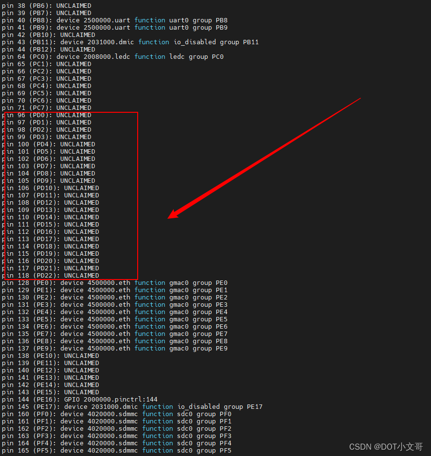
是否遗漏某些地方配置不当或者设备树修改错误了?
使用的是sun20iw1p1.dtsi里面的rgb18_pins_a
初步分析
好像是因为没在linux源码仓库添加st7701_rgb的驱动。
先试试加上st7701_rgb的驱动
即使改成了rgb18_20_pins_a ,也没能将io初始化
pin 140 (PE12): UNCLAIMED
pin 141 (PE13): UNCLAIMED
pin 142 (PE14): UNCLAIMED
pin 143 (PE15): UNCLAIMED
感觉 st7701s_rgb.c 没有编译,你看下
find . -name st7701s_rgb.o
实际上也编译进去了


再次尝试
使用仓库:https://github.com/Tina-Linux/tina-d1x-lichee-rv,编译依旧不通过
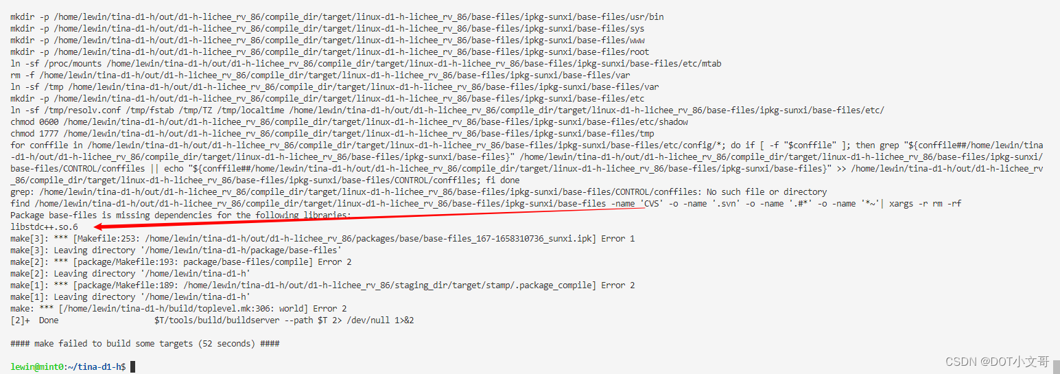
也尝试针对你仓库的代码,修改以下文件
tina-d1-h/device/config/chips/d1-h/configs/nezha/linux-5.4/board.dts
tina-d1-h/lichee/linux-5.4/drivers/video/fbdev/sunxi/disp2/disp/Makefile
tina-d1-h/lichee/linux-5.4/drivers/video/fbdev/sunxi/disp2/disp/lcd/Kconfig
tina-d1-h/lichee/linux-5.4/drivers/video/fbdev/sunxi/disp2/disp/lcd/panels.c
tina-d1-h/lichee/linux-5.4/drivers/video/fbdev/sunxi/disp2/disp/lcd/panels.h
tina-d1-h/lichee/linux-5.4/drivers/video/fbdev/sunxi/disp2/disp/lcd/st7701s_rgb.c
tina-d1-h/lichee/linux-5.4/drivers/video/fbdev/sunxi/disp2/disp/lcd/st7701s_rgb.h
结果 lcd的io也是没有初始化
再再尝试
看到有大佬分析:lcd rgb gpio是在你们屏驱动st7701s_rgb中调用sunxi_lcd_pin_cfg(sel, 1);初始化的,可以跟下调用流程,试一下发现连这个printk都没有打印,好像都没有进入probe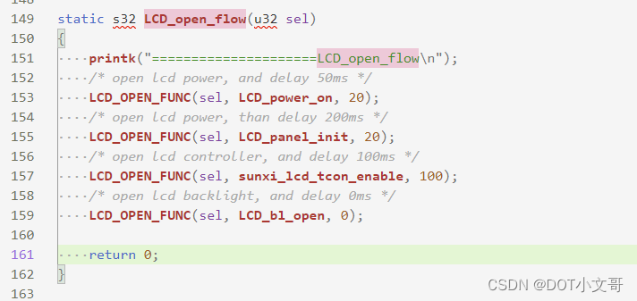
开机过程中在uboot初始化lcd后,kernel是不是走lcd初始化流程的,进入内核后,休眠唤醒一下lcd,看看pin脚状态有没有变化
mount -t debugfs none /sys/kernel/debug
cd /sys/kernel/debug/dispdbg
//休眠
echo suspend > command; echo disp0 > name; echo 1 > start
//唤醒
echo resume > command; echo disp0 > name; echo 1 > start
使用以上指令,lcd部分管脚配置成功了。lcd_gpio_0、lcd_gpio_1、lcd_gpio_2、lcd_gpio_3,这四个gpio没有初始化正常。
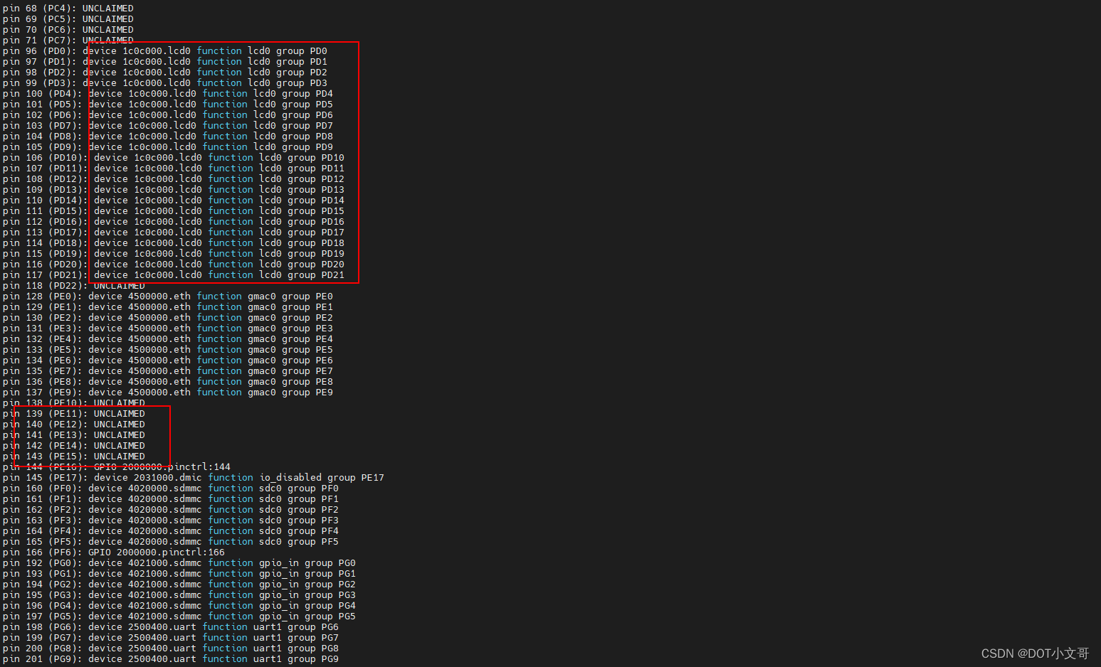
以下是执行唤醒lcd的log

lcd的显示情况如下:
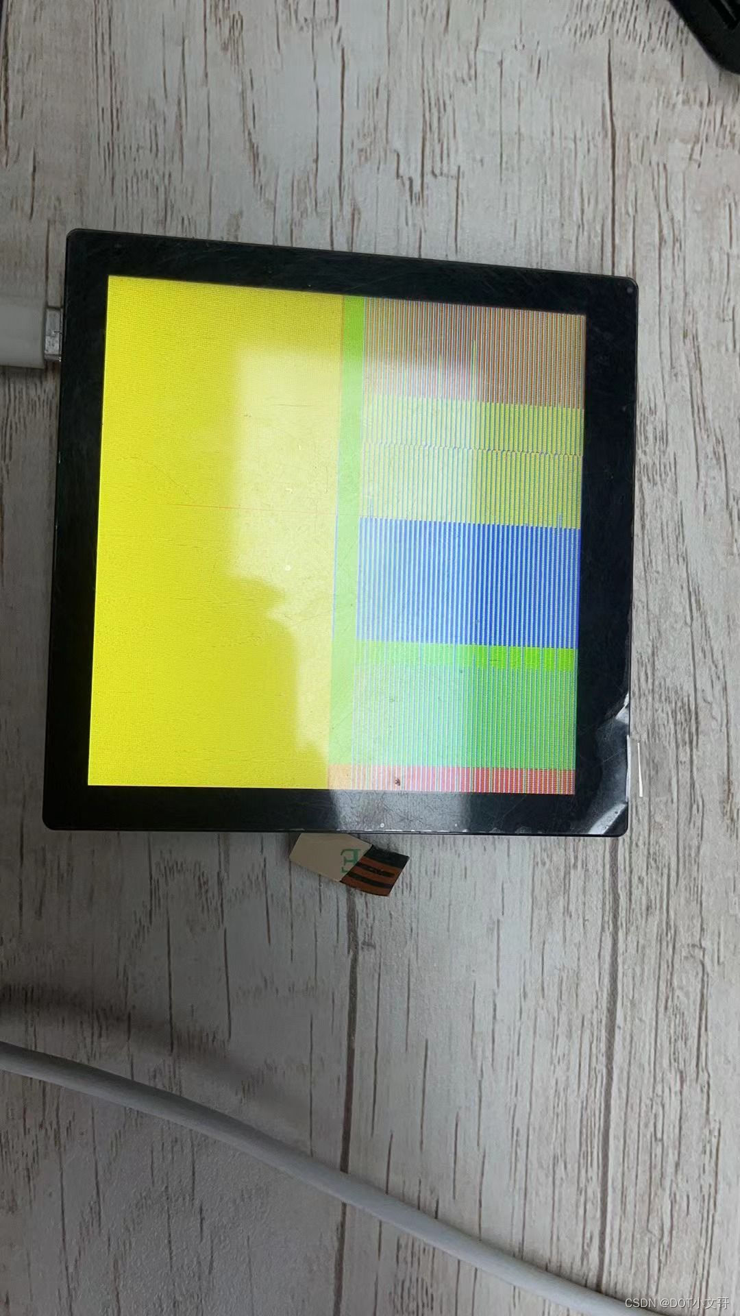
最终结果
- 将uboot-board.dts的lcd注释掉,colorbar不在闪屏。
- lcd_gpio_0、lcd_gpio_1、lcd_gpio_2、lcd_gpio_3,依旧没能初始化。原因未知。
目前显示效果如下:
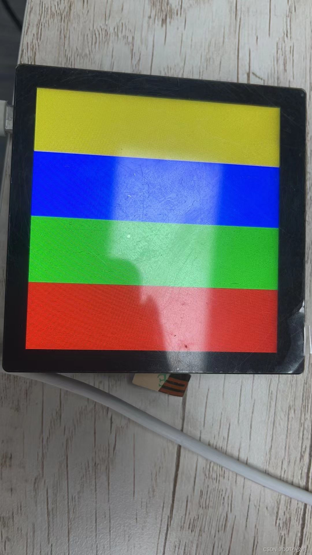
请使用quilt应用该patch
原文链接:https://bbs.aw-ol.com/topic/1772/
 /9
/9 