高度可靠的霍耳传感器接口集成方案
A Fully Integrated, Robust Solution for Interfacing with Hall-Effect Sensors
Abstract: This article provides an overview of Hall-effect sensors, particularly the use of two-wire, Hall-effect digital switches in automotive and industrial applications. It then details a method for adding diagnostic capabilities and robust protection to automotive and industrial applications using a fully integrated Hall-effect sensor interface. Test results for immunity to ground shifts are also provided.
IntroductionThe Hall effect refers to the principle that when a magnetic field is applied perpendicularly to a current-carrying conductor, a difference in potential appears on opposite sides of the conductor through which the electric current is flowing.
Based upon this principle, Hall-effect sensors detect changes in the magnet field and provide a proportional output voltage. They thus allow contactless sensing and, consequently, can be deployed in robust packages that protect against environmental elements.
Because they provide increased reliability in harsh environments, Hall-effect sensors are used in a wide range of industrial and automotive applications from motor-speed control for window lifters and sunroofs to on-off switch detection for doors and key ignition.
Types of Hall SensorsThere are a variety of Hall-effect sensors available today such as three-wire and two-wire digital sensors, linear sensors, current sensors, and bipolar or unipolar digital switches. Two-wire sensors have two connections: one for the supply/output and the other for ground, as opposed to three-wire sensors that use an individual connection for the supply and the output.
Two-wire, Hall-effect digital switches are commonly used in automotive and industrial applications in which noise immunity is an important consideration and in which the Hall sensor is remote from the associated electronics. This form of current-mode signaling is highly immune to noise and facilitates simple diagnostics, since a working Hall sensor will always draw some current.
These sensors provide two distinct levels of current depending on whether the magnetic field is applied or not. While current levels vary depending on the sensor manufacturer, they typically range from 5mA to 8mA for low-level (no magnetic field) and 11mA to 14mA for high-level (presence of magnetic field) signals.
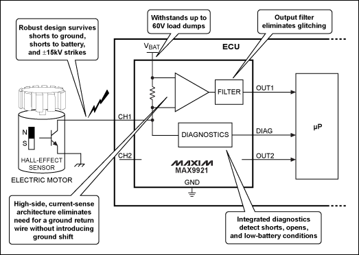
Hall-Effect Sensor InterfaceThe MAX9921 is the first fully integrated solution that interfaces two-wire, Hall-effect digital switches to a microcontroller. It features two independent channels, provides the current path for the two sensors, monitors their current levels, and generates one digital output per channel for the microcontroller through open-drain outputs. Figure 1 shows the block diagram and typical application circuit for the device.

Figure 1. A block diagram and typical application circuit using the MAX9921 is shown.
A robust IC, the MAX9921 is designed to withstand harsh operating environments such as the ones found in industrial and automotive applications. The device operates from a 6V to 18V battery-voltage range, but can survive supply transients (load dumps) up to 60V. Additionally, the Hall inputs integrate protection against shorts to ground, shorts to the supply voltage, and electrostatic-discharge (ESD) spikes up to ±15kV. This built-in input protection eliminates the need for external circuitry, thus saving cost and space.
The MAX9921's two channels operate independently, allowing the device to provide diagnostics and fault protection on each input. In diagnostic mode, the diagnostic output is combined with the two individual channel outputs to provide basic diagnostics and monitor sensor status. Specifically, the diagnostic functions include: input open (no sensor is connected), input shorted to ground, input shorted to the battery supply voltage (VBAT), and VBAT is out of range. The diagnostics are capable of distinguishing which one of the two inputs is affected by any of the above conditions. The integration of a diagnostic output eliminates the need for performing this functionality in firmware and the expense of using an analog-to-digital converter (ADC) inside the microcontroller to measure the Hall current.
Ground-Shift Immunity Reduces WiringAlthough the MAX9921 targets applications that use two-wire Hall-effect sensors, the device can also be used as a single-wire interface to Hall sensors. Its high-side current-sensing topology makes it immune to shifts between the sensor ground and the ground of the MAX9921 and microcontroller. This ground-shift immunity eliminates the need for a ground-connection wire (the chassis-ground connection in automobiles, for example), thus allowing a single-wire interface to the Hall sensor.
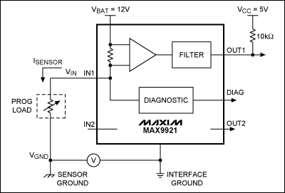
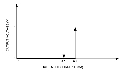
Figure 2 presents a circuit used for testing the MAX9921's immunity to ground shifts. Instead of a Hall-effect sensor, the circuit employs a programmable load, which functions as a current sink where the current can be programmed in several ranges, with a resolution of 0.1% of the selected full-scale value. A 10mA full-scale value was chosen for this experiment, with resolution down to 10μA. As Figure 3 demonstrates, the MAX9921 exhibits current thresholds with hysteresis just less than 1mA to ensure reliable operation in harsh or noisy environments.

Figure 2. A circuit used for testing the MAX9921's immunity to ground shifts is shown.

Figure 3. The MAX9921's current thresholds and hysteresis are shown.
In the first experiment, the current flowing in the programmable load was set to 9.05mA, which is only 50μA below the threshold that would switch the MAX9921 output from low (~0V) to high (~5V with a pullup resistor connected to 5V). The ground of the programmable load was shifted up and down versus the MAX9921's ground with a DC voltage generator (V). As shown in Table 1, with VBAT = 12V, the MAX9921's threshold was immune to ground shifts up to ±8V!
Table 1. Immunity to Ground Shifts with a 9.05mA Current Threshold
| ISENSOR (mA) |
VGND (V) |
VIN (V) |
VOUT (V) |
| 9.05 |
-8 |
10.8 |
0 |
| -4 |
| -2 |
| 0 |
| +2 |
| +4 |
| +8 |
10.9 |
A similar experiment was conducted to test the robustness of the 8.2mA high-to-low current threshold. The current was programmed to 8.25mA, and again the MAX9921 output did not switch even for ground shifts up to ±8V (Table 2).
Table 2. Immunity to Ground Shifts with an 8.2mA Current Threshold
| ISENSOR (mA) |
VGND (V) |
VIN (V) |
VOUT (V) |
| 8.25 |
-8 |
10.8 |
5 |
| -4 |
| -2 |
| 0 |
| +2 |
| +4 |
| +8 |
10.9 |
The MAX9921's high-side current-sense topology makes the device immune to ground shifts up to ±8V between the sensor and the interface. This capability is particularly important in applications where the Hall-effect sensor is far away from the place where the logic (MAX9921 interface and microcontroller) resides. In cases like this, the MAX9921 eliminates the need for a ground wire between itself and the Hall-effect sensor, thus saving cost and space.
ConclusionThe MAX9921's ground-shift immunity, input protection, ability to withstand up to 60V, and diagnostic capabilities allow the MAX9921 to provide a fully integrated, compact, and robust solution for interfacing Hall-effect sensors to microcontrollers in harsh environments, such as those found in automotive and industrial applications. |
 0
0
|
|
|
|
|
|
|
 /9
/9 


 淘帖
淘帖 1894
1894

