中断的作用场景、流程及优特点:

中断系统的结构:
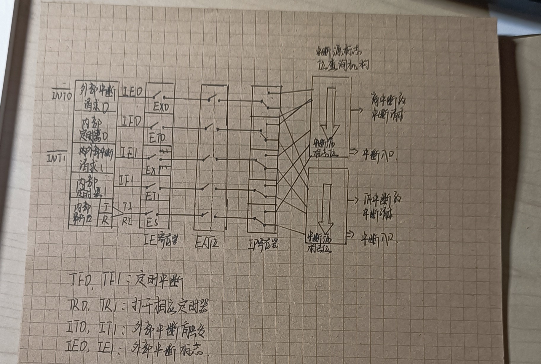
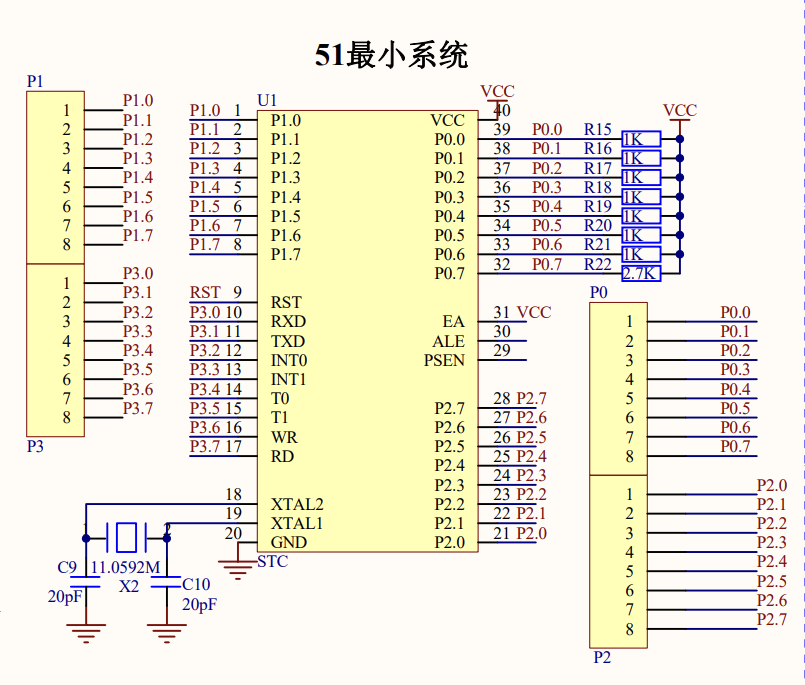
当采用外部中断0(INT0)时,,杜邦线就要连接P3.2引脚,,在编写代码过程中就用EX0和IT0;
若采用外部中断1(INT1)时,杜邦线就要连接P3.3引脚,,在编写代码过程中就用EX1和IT1;
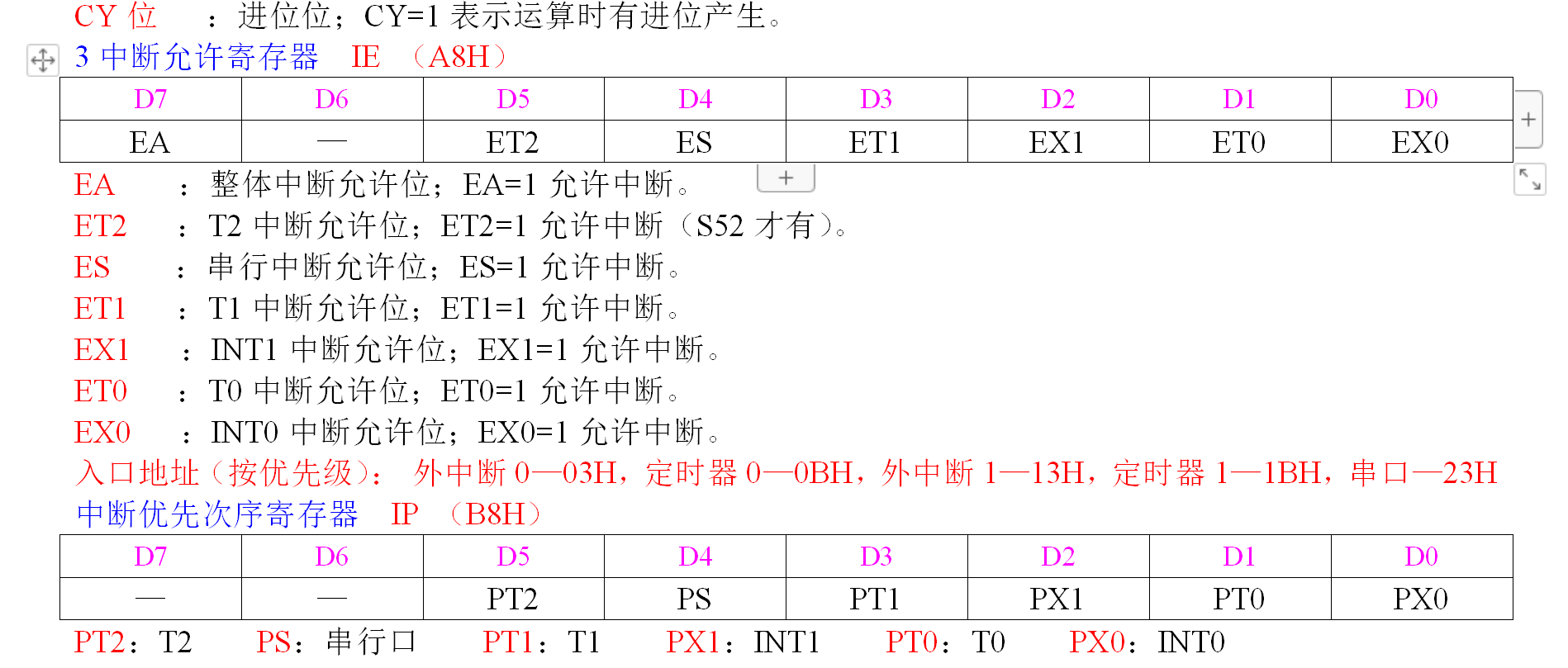
高电平打开,低电平关闭
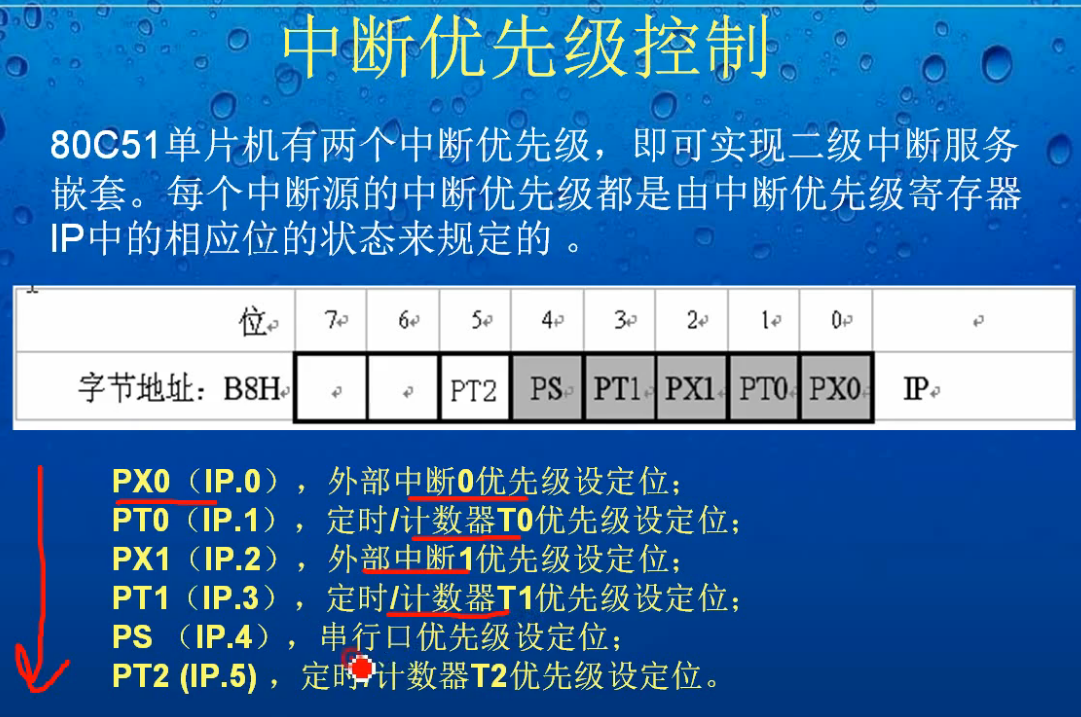
与中断函数interrupt写入有关
如:当采用外部中断0时,函数名为:interrupt 0
中断函数与普通函数的相同点:
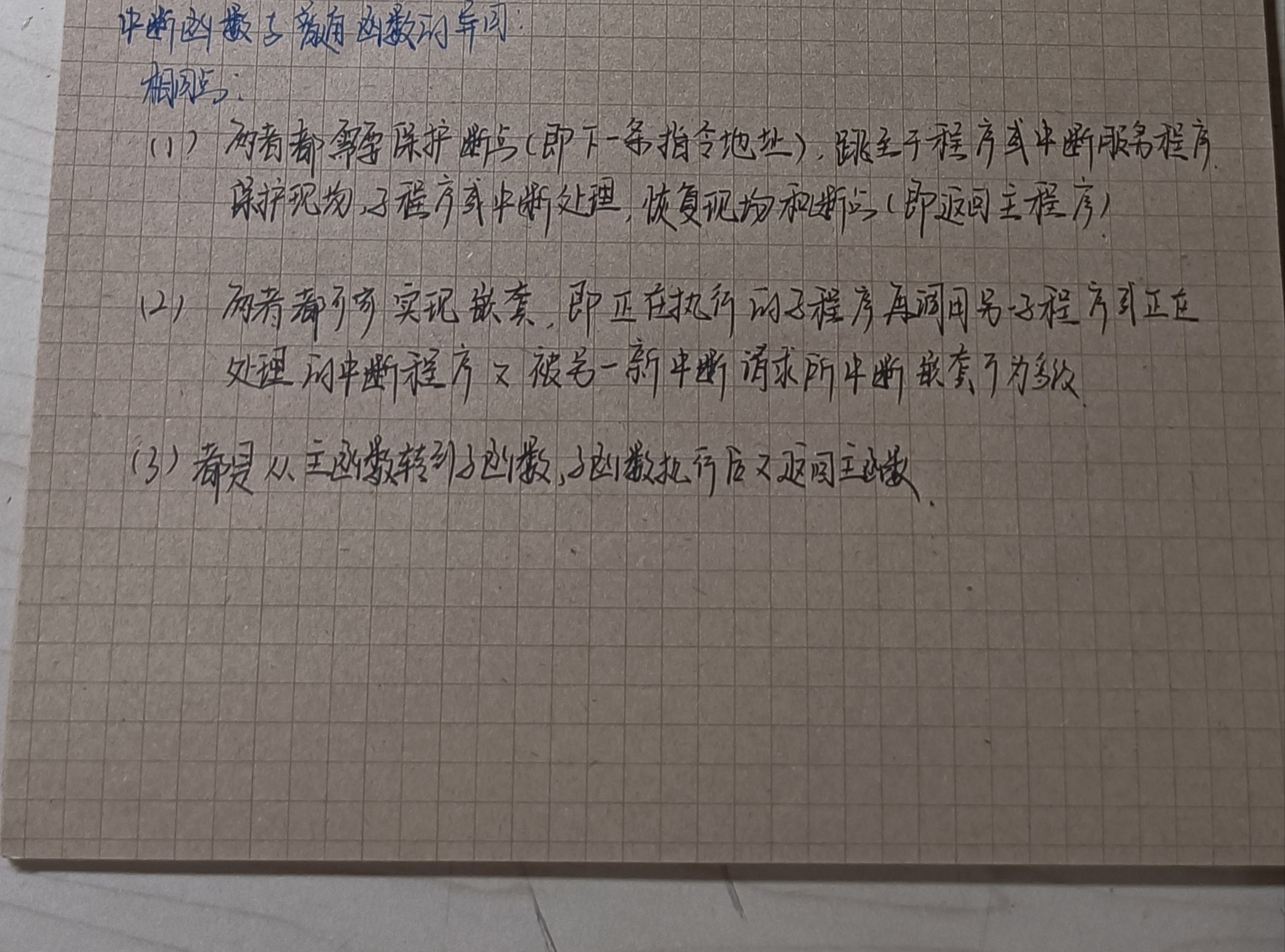
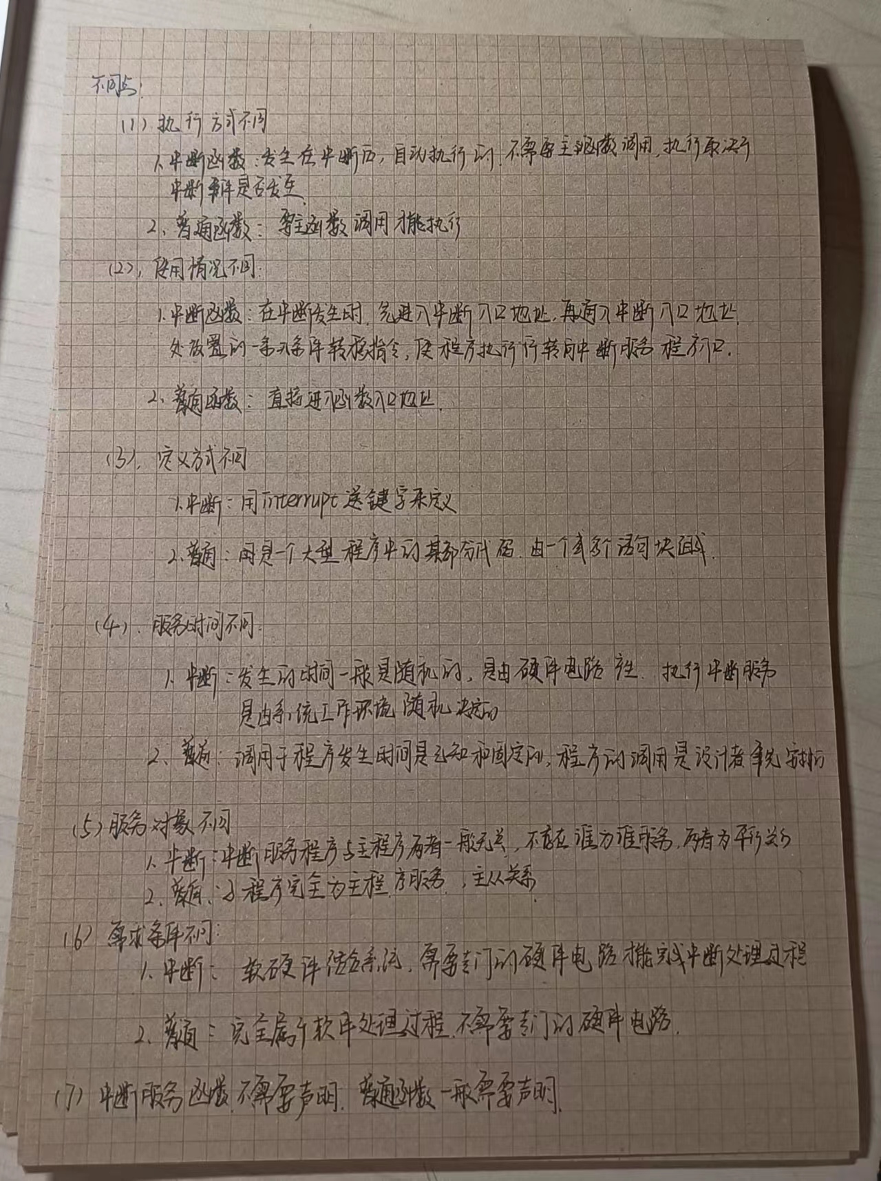
中断函数与普通函数的不同点:
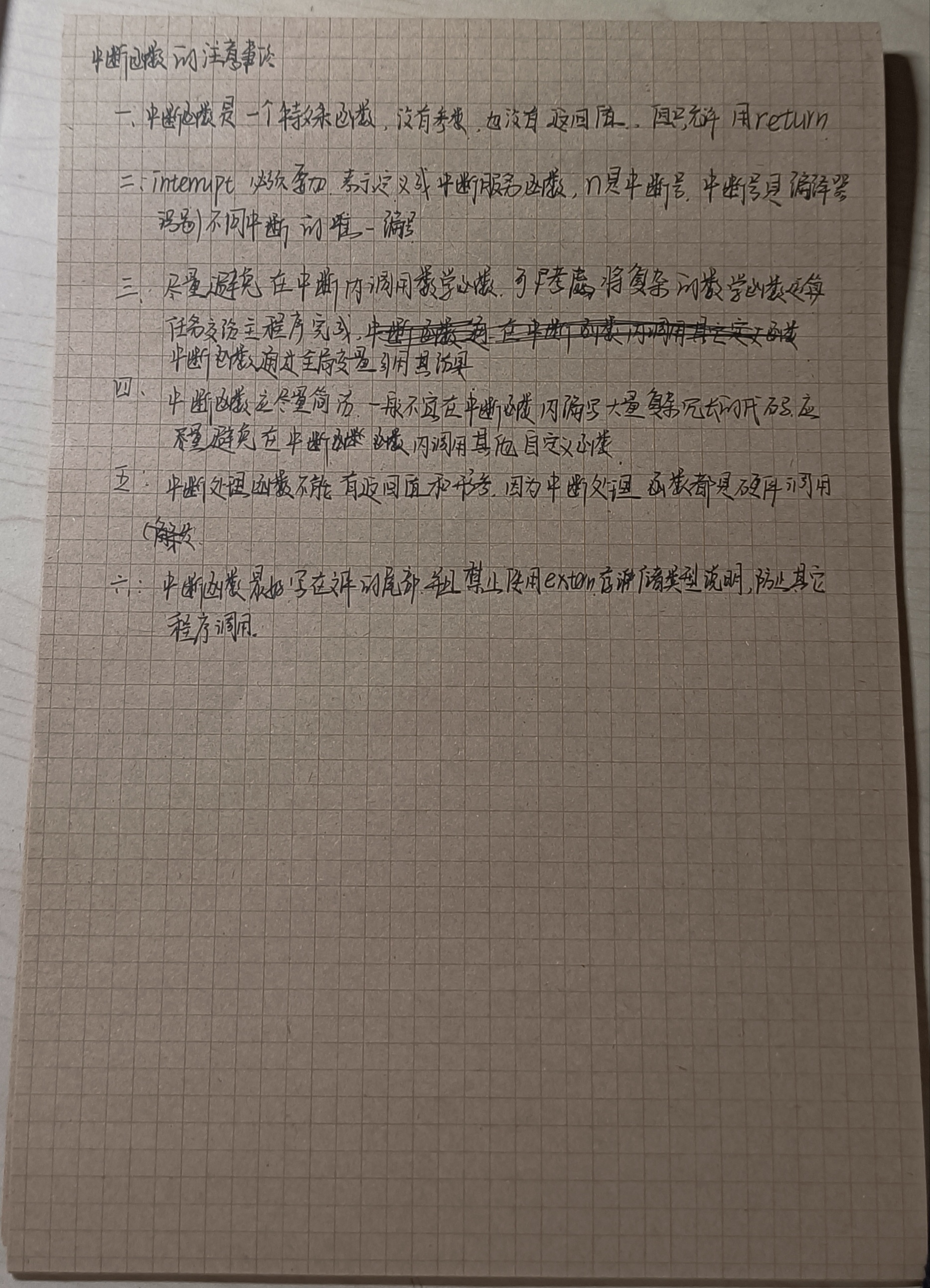
中断函数的注意事项:
用chatGDP用中断函数编写用数码管显示学号后三位例程:
#include <reg51.h>
sbit LED_A = P2^0;
sbit LED_B = P2^1;
sbit LED_C = P2^2;
sbit LED_D = P2^3;
sbit LED_E = P2^4;
sbit LED_F = P2^5;
sbit LED_G = P2^6;
sbit LED_DP = P2^7;
sbit KEY = P3^2;
unsigned char code LED_Num[10] = {
0xc0,
0xf9,
0xa4,
0xb0,
0x99,
0x92,
0x82,
0xf8,
0x80,
0x90
};
void delay(unsigned int t) {
while(t--);
}
void display(unsigned char num) {
P0 = LED_Num[num];
}
void main() {
EA = 1;
EX0 = 1;
IT0 = 1;
while(1) {
display(1);
}
}
void interrupt0() interrupt 0 {
if (KEY == 0) {
delay(1000);
if (KEY == 0) {
display(3);
delay(1000);
display(5);
delay(1000);
display(0);
}
}
}
修改代码思路:
1、BST-M51单片机数码管段选引脚是为P0,因此将P2引脚全改为P0;
2、M51单片机外部中断触发按钮为P3^4~P3^7, 因此将触发引脚改为P3^6;
3、M51单片机LED数码管结构为共阴极,因此将数码管段选值改为共阴极显示;
4、将延时函数改为熟知的;
此时将代码烧录进单片机中, 用杜邦线连接P3^3和P3^6,此时数码管显示4个1,按动中断按键K4,发现数字闪动过快,因此,需要加大延时;
5、将各个数字的延时调大到10000000;
再烧录进去,此时数码管显示四个1,按动K4后,数字350依次显示;
修改后代码
#include <reg51.h>
sbit LED_A = P0^0;
sbit LED_B = P0^1;
sbit LED_C = P0^2;
sbit LED_D = P0^3;
sbit LED_E = P0^4;
sbit LED_F = P0^5;
sbit LED_G = P0^6;
sbit LED_DP = P0^7;
sbit KEY = P3^6;
unsigned char code LED_Num[17] = {0xbf,0x86,0xbd,0xcf,0xe6,0xed,0xfd,0x87,0xff,0xef,0xf7,0xfc,0xb9,0xde,0xf9,0xf1 };
void delay(unsigned int t) {
while(t--);
}
void display(unsigned char num) {
P0 = LED_Num[num];
}
void main() {
EA = 1;
EX1 = 1;
IT1 = 1;
while(1) {
display(8);
}
}
void interrupt0() interrupt 0 {
if (KEY == 0) {
delay(1000);
if (KEY == 0) {
display(3);
delay(100000);
display(5);
delay(10000000);
display(0);
delay(10000000);
}
}
}
 /9
/9 