摘要:本应用笔记解释了如何通过选择合适的外部元件来实现为其他模块供电的升压电压,从而构建集成升压转换器功率级。
介绍
当系统具有高功率要求时,开关稳压器始终是首选。它们提供高效率和紧凑的 PCB 解决方案尺寸,以实现令人满意的电源。本应用笔记提供的方程式可指导在实现升压电压时选择升压开关稳压器所需的外部元件。
升压转换器配置
作为图1所示的基本升压开关稳压器配置,当低端开关在时钟开关周期开始时导通时,高边开关同时关断。V断续器等于接地电压;当低端开关关闭时,高边开关在时钟切换周期的静止时间间隔内导通,并且V断续器等于输出电压 V 外 ,忽略了开关电流I引入的高压侧和低压侧功率FET上的压降房 协和我断续器分别流经环路。出现在V上的方波信号断续器通过LC滤波器,产生恒定输出电压V 外 ,由 V 的占空比 D 控制 断续器 .
同时,在低端开关导通时间间隔期间,电感电流I断续器斜坡上升以存储电感器的能量,并且与高端开关的ON时间间隔相反,I断续器斜坡下降以提供存储在电感器内部的能量,以维持输出负载。
 图 1.升压转换器配置
 图 2.升压转换器波形
选择电感器
当处于连续导通模式时,电源开关在开关周期中的每个状态下都会消耗功率损耗。增加的电感电流仍然等于降低的电感电流。占空比按以下公式排列:
 等式 (1)
其中参数为:V 外 : 稳压输出电压V 在 : 电源输入电压V 电除尘器 : HS 开关V 两端的压降 DS2 : Voltage drop across LS switch
The duty cycle is determined simply by the input voltage and output voltage when neglecting the VDS1 and V DS2 :
 Equation (2)
The higher inductance value generates a smaller current ripple ΔILX and peak current value I PEAK , which determines the maximum load current the switching regulator IC outputs, also inducing a smaller input voltage ripple. The IPEAK should be less than the minimum value of the ILIM the IC can provide.
The switching regulator IC data sheet provides the inductor selection range, normally a fixed nominal value \pm tolerance%, and the device internal slope compensation is optimized for the external inductor value selected within the acceptable range. Once the inductor value is selected, the peak current is derived as DC input load plus half inductor ripple current.
The inductor ripple current and peak current are expressed as:
 Equation (3)
 Equation (4)
where the parameters are:V IN : Supply input voltageD: Duty cycle derived from Equation (2)f sw : Switching frequency on systemL: Inductor valueI LOAD : Load current required from IC
The root mean square (RMS) current flowing through the inductor is:
 Equation (5)
where the parameters are:I LOAD : Load current required from ICΔI LX : Inductor ripple current calculated value from Equation (3)
Select inductors having a higher RMS current rating to avoid overheating impacting the efficiency and performance. The saturation current of the inductor stated from the data sheet should be larger than the maximum value of IPEAK in a given range of VIN so that the inductance value does not drop too much by a certain number. Smaller inductor value has low cost and saves PCB area, but has larger current ripple, conducting more AC core power loss dissipated on it, combining with the conduction power loss from the DCR value of the inductor. The significant power dissipated on inductor also heat ups the whole compact solution area, lowering efficiency, especially for heavy input average current.
Selecting the Input Capacitor
The input voltage ripple is contributed by the capacitor elements capacitance and equivalent series resistance (ESR) in steady state. Use low ESR, X7R ceramic capacitors to minimize the input voltage ripple.
The input capacitance with a specific input voltage ripple is expressed as:
 Equation (6)
where the parameters are:ΔI LX : Inductor ripple current calculated value from Equation (3)f sw : Switching frequency on systemΔV IN : Input voltage ripple requirement
The input voltage ripple contribution from ESR is expressed as:
 Equation (7)
where the parameters are:ΔI LX : Inductor ripple current calculated value from Equation (3)R ESR : Equivalent series resistance of input capacitors
The actual ceramic capacitance should be larger than the value calculated above to give some margin on the capacitance loss by DC bias voltage derating. Follow the data sheet component selection guide for minimum ceramic capacitance needed to stabilize the input voltage. One 0.1µF ceramic capacitor should be preferably placed in parallel, decoupling high frequency noise on input. Add aluminum bulk capacitance to provide large current during load transient and keep an allowable input voltage deviation.
Selecting the Output Capacitor
When the high-side switch is in the ON state, the switching current flowing on the IC output path carries switching noise, and the output capacitor filters out most noise effectively and reduces output voltage ripple. The larger the load current, the larger the voltage ripple that is seen on the output. Place the output capacitor as close to the switching regulator as possible.
Calculate the output capacitance for a specified output voltage ripple as:
 Equation (8)
where the parameters are:I LOAD : Load current required from ICD: Duty cycle derived from Equation (2)f 西 南部 : 系统上的开关频率 ΔV 外 : 输出电压纹波要求
ESR的输出电压纹波贡献表示为:
 等式 (9)
其中参数为:I 负荷 :ICD所需的负载电流:占空比由公式(2)ΔI得出 断续器 :电感纹波电流计算值,取自公式(3)R 断续器 :输出电容网络的等效串联电阻
使用低ESR陶瓷电容器,当大纹波电流流过输出电容器时,将输出电压纹波降至最低。X7R电介质材料具有更好的温度特性,可处理电容器随温度升高引起的较小电容变化。
调整输出电压
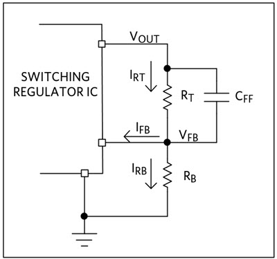
输出电压由固定的内部电阻分压器设定,或由外部电阻网络调节(如果适用),并反馈至开关稳压器IC。当前一期室温流经顶部电阻RT应大于漏电流I的100倍断续器进入IC的反馈引脚,以保持输出端的电压精度。添加一个小的前馈电容器 C断续器与顶部电阻 R 并联T在反馈环路中产生升压零点,以优化相位裕量。
按照数据手册选择推荐的底部电阻RB在图3中,以较小的kΩ为单位。然后,顶部电阻RT计算公式为:
 等式 (10)
其中参数为:R B :可调电阻分压器网络中的底部电阻,如数据表V所示 外 : 所需输出电压V 断续器 : 稳压反馈电压
 图 3.可调电阻分压器网络配置
功耗
在特定工况下,输出功率P外在给定的输出电压 V 下固定外和负载电流 I 外 ,系统的功率损耗PLOSS越小,效率η(η= P 外 /(P 外 + P 损失 )).电感器的功率损耗包括直流导通损耗(I外 ^2^ × R 断续器 )和交流磁芯损耗,这是由电感器制造商在公式(11)中忽略的特定电感功率模型上提供的。
开关稳压器IC上的功耗表示为:
 等式 (11)
其中参数为:V 外 :稳压输出电压D:占空比由公式(2)I得出 负荷 : ICη所需的负载电流:稳压器R的效率 断续器 : 电感直流电阻
器件内部的功耗转化为热量,增加结温。芯片 T 的结温J超过工作温度 T 的最大限值杰马克斯如数据手册所示,会降低使用寿命并影响产品可靠性。
估计给定环境 T 中的结温 一个 :
 等式 (12)
其中参数为:T 一个 : 环境温度Θ 断续器 : 数据表P 中建议的结与环境温度的热阻 损失 :公式(11)中器件内部的功率损耗
 /7
/7 