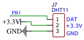
在饭盒派的开发板上,配有温度传感器DHT11的接口,见图1所示。

图1 传感器接口
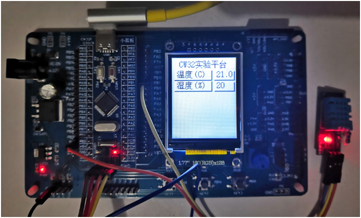
稍感不足的是,该接口与传感器DHT11功能模块的连接并不友好,会因为引脚排列的问题导致传感器模块无法直接进行插接使用,只好通过杜邦线来连接器件和接口,其连接与显示效果如图2所示。

图2 器件连接及显示效果
有接口电路可知,DHT11的 IO口所连接的引脚为PB1。
配置DHT11所用引脚的函数为:
uint8_t DHT11_GPIO_Config ( void )
{
    GPIO_InitTypeDef GPIO_InitStruct;
    __RCC_GPIOB_CLK_ENABLE();
    GPIO_InitStruct.IT= GPIO_IT_NONE;
    GPIO_InitStruct.Mode= GPIO_MODE_OUTPUT_PP;
    GPIO_InitStruct.Pins= GPIO_PIN_1;
    GPIO_InitStruct.Speed= GPIO_SPEED_HIGH;
    GPIO_Init(CW_GPIOB,&GPIO_InitStruct);
}
通过IO口对DHT11输出复位信号的函数为:
void DHT11_Rst(void)
{
PB01_DIR_OUTPUT();
PB01_SETLOW();
delay1ms(20);
PB01_SETHIGH();
delay10us(3);
}
等待DHT11回应的函数为:
uint8_t DHT11_Check(void)
{
uint8_t retry=0;
PB01_DIR_INPUT();
while(PB01_GETVALUE()&&retry<10)
{
retry++;
delay10us(1);
};
if(retry>=10)return 1;
else retry=0;
while(!PB01_GETVALUE()&&retry<10)
{
retry++;
delay10us(1);
};
if(retry>=10)return 1;
return 0;
}
从DHT11读取数据的函数为:
uint8_t DHT11_Read_Data(float *temp,uint8_t *humi)
{
char buf[5];
uint8_t i;
DHT11_Rst();
if(DHT11_Check()==0)
{
for(i=0;i<5;i++)
{
buf[i]=DHT11_Read_Byte();
}
if((buf[0]+buf[1]+buf[2]+buf[3])==buf[4])
{
*humi=buf[0];
*temp=buf[2];
}
}else return 1;
return 0;
}
实现图2所示效果的主程序为:
int main()
{
RCC_Configuration();
GPIO_Configuration();
BTIM_init();
Lcd_Init();
Lcd_Clear(GRAY0);
Redraw_Mainmenu();
while(DHT11_GPIO_Config());
while(1)
{
if(counttime>200)
{
counttime=0;
DHT11_Read_Data(&temperature,&humidity);
sprintf(buff_1,"%0.1f",temperature);
sprintf(buff_2,"%d",humidity);
Gui_DrawFont_GBK16(90,25,BLUE,GRAY0,buff_1);
Gui_DrawFont_GBK16(90,47,BLUE,GRAY0,buff_2);
}
}
}
这样在开发板上就轻松地实现了温湿度的检测及显示功能,其界面效果还是比较典型的。
 /6
/6 