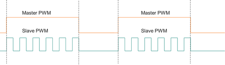
要实现主从模式,根据主 PWM 信号的上升沿和下降沿控制从机 PWM 信号,可以将 GTM(通用计时器模块)的 ARU(高级路由器单元)与 ATOM(定时器输出模块)结合使用,生成 PWM 信号。
以下示例代码演示如何配置和使用 GTM ATOM 生成主 PWM 信号并控制从属 PWM 信号:
#include "Ifx_Types.h"#include "IfxCpu.h"#include "IfxScuWdt.h"#include "GTM_ATOM_PWM.h"#include "Bsp.h"#define MASTER_PWM_CHANNEL 2#define SLAVE_PWM_CHANNEL 5IfxGtm_Atom_Pwm_Config masterConfig;IfxGtm_Atom_Pwm_Config slaveConfig;IfxGtm_Atom_Pwm_Driver masterDriver;IfxGtm_Atom_Pwm_Driver slaveDriver;void initGtmAtomPwm(void){ // Enable the GTM IfxGtm_enable( MODULE_GTM); // Set the CMU clock 0 frequency to 1 MHz IfxGtm_Cmu_setClkFrequency( MODULE_GTM, IfxGtm_Cmu_Clk_0, 1000000); // Enable the CMU clock 0 IfxGtm_Cmu_enableClocks( MODULE_GTM, IFXGTM_CMU_CLKEN_CLK0); // Initialize the master PWM configuration IfxGtm_Atom_Pwm_initConfig( masterConfig, MODULE_GTM); masterConfig.atom = IfxGtm_ATOM2; masterConfig.atomChannel = MASTER_PWM_CHANNEL; masterConfig.period = 5000; // Set the period for the master PWM signal masterConfig.pin.outputPin = LED; // Set the LED as the output pin for the master PWM signal masterConfig.synchronousUpdateEnabled = TRUE; // Enable synchronous update of the timer // Initialize and activate the master PWM IfxGtm_Atom_Pwm_init( masterDriver, masterConfig); IfxGtm_Atom_Pwm_start( masterDriver, TRUE); // Initialize the slave PWM configuration IfxGtm_Atom_Pwm_initConfig( slaveConfig, MODULE_GTM); slaveConfig.atom = IfxGtm_ATOM2; slaveConfig.atomChannel = SLAVE_PWM_CHANNEL; slaveConfig.period = 5000; // Set the period for the slave PWM signal slaveConfig.pin.outputPin = SLAVE_LED; // Set the slave LED as the output pin for the slave PWM signal slaveConfig.synchronousUpdateEnabled = TRUE; // Enable synchronous update of the timer // Initialize and activate the slave PWM IfxGtm_Atom_Pwm_init( slaveDriver, slaveConfig); IfxGtm_Atom_Pwm_start( slaveDriver, TRUE);}int main(void){ // Enable interrupts IfxCpu_enableInterrupts(); // Disable the watchdog IfxScuWdt_disableCpuWatchdog(IfxScuWdt_getCpuWatchdogPassword()); // Initialize the GTM ATOM PWM initGtmAtomPwm(); while (1) { // Your application code here } return 0;}在此代码中,该initGtmAtomPwm 函数用于配置和初始化 GTM ATOM 以生成主机和从 PWM 信号。主 PWM 信号使用 和masterConfig masterDriver结构生成,而从属 PWM slaveConfig信号slaveDriver使用 和 结构生成。period配置结构中的 字段用于设置 PWM 信号的周pin.outputPin期,该 字段用于选择 LED 作为 PWM 信号的输出引脚。
请注意,您需要将LED SLAVE_LED和 替换为适合您的特定硬件设置的引脚定义。
GTM ATOM 初始化后,您就可以使用该IfxGtm_Atom_Pwm_start 功能启动主 PWM 信号和从机 PWM 信号的 PWM 生成。然后,您可以通过使用所需的导通时间值调用 PWM 信号的占空比来控制 PWMIfxGtm_Atom_PwmHl_updatePulse 信号的占空比。
请注意,此代码是一个基本示例,可能需要修改以适应您的特定要求和硬件设置。

 举报
举报