*附件:mbmxxs-p50-x_user_guide_r1.0[1].pdf
The MBMxxS-P50-x is an evaluation kit for the BMUxxS-P50-x, a reference design board for a 7-cell to 16-cell in series battery management unit.
This board uses the MP279x ICs, a robust family of battery management analog front-ends (AFEs) that provide a complete AFE monitoring and protection solution. The MP279x supports up to 16 cells in series, and provides two separate analog-to-digital converters (ADCs) for synchronous voltage and current measurements. The high-side MOSFET (HS-FET) driver and robust HW protection functions come with configurable thresholds. Protections include over-current protection (OCP), short-circuit protection (SCP), battery and cell over-voltage protection (OVP), battery and cell under-voltage protection (UVP), over-temperature protection (OTP), and under-temperature protection (UTP). The MP279x also integrates internal balancing FETs to equalize mismatched cells while offering the option to control external FETs for a higher balancing current.
The board also features the MPF4279x, a standalone battery fuel gauge (FG) IC that performs state-of-charge (SoC), time-to-full, time-to-empty, and unavailable energy estimation using a custom battery model obtained through exhaustive characterization and voltage, current, and temperature readings. This solution is fast, simple, and easy to configure through the graphic user interface (GUI). Figure 1 shows the MBMxxS-P50-X block diagram.
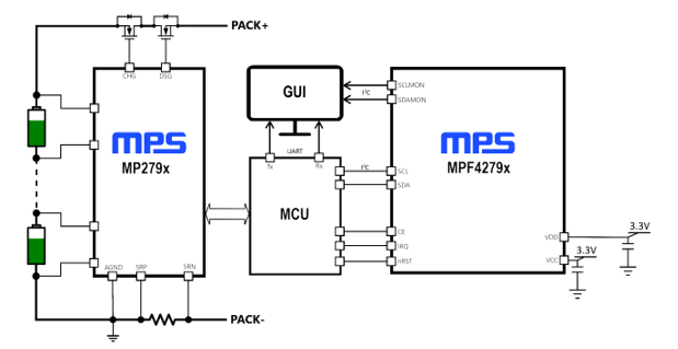
Figure 1: MBMxxS-P50-x Block Diagram Design
Each MBMxxS-P50-x evaluation board offers a different combination of the MP279x AFE and the MPF4279x fuel gauge. See the Evaluation Kits section on page 5 for more details.
| Reference Design | MPF4279x Part Number | MPF4279x Short Description | MP279x Part Number | MP279x Short Description |
|---|---|---|---|---|
| MBM16S-P50 | MPF42790 | 2-Cell to 16-Cell FG with Level LEDs | MP2797 | 7-Cell to 16-Cell BMS with I^2^C |
| MBM14S-P50 | MPF42790 | 2-Cell to 14-Cell FG with Level LEDs | MP2791 | 7-Cell to 14-Cell BMS with I^2^C |
| MBM10S-P50 | MPF42795 | 2-Cell to 10-Cell FG with Level LEDs | MP2791 | 7-Cell to 14-Cell BMS with I^2^C |
| MBM16S-P50-B | MPF42791 | Next Generation 2-Cell to 16-Cell FG with Level LEDs | MP2797 | 7-Cell to 16-Cell BMS with I^2^C |
| MBM14S-P50-B | MPF42791 | Next Generation 2-Cell to 14-Cell FG with Level LEDs | MP2791 | 7-Cell to 14-Cell BMS with I^2^C |
Items included with the kit (items below can be ordered separately):
| # | Part Number | Item | Quantity |
|---|---|---|---|
| 1 | BMU16S-P50-R01A | MP2797DFP-0001-T and MPF42790DRT-0B-0001 or MPF42792DRT-0B-0001 reference design and evaluation board | 1 |
| 2 | EVKT-USB_RS232/I2C-01 | USB to RS232 / I^2^C adapter | 1 |
Items included with the kit (items below can be ordered separately):
| # | Part Number | Item | Quantity |
|---|---|---|---|
| 1 | BMU14S-P50-R01A | MP2791DFP-0001-T and MPF42790DRT-0B-0001 or reference design and evaluation board | 1 |
| 2 | EVKT-USB_RS232/I2C-01 | USB to RS232 / I^2^C adapter | 1 |
Items included with the kit (items below can be ordered separately):
| # | Part Number | Item | Quantity |
|---|---|---|---|
| 1 | BMU10S-P50-R01A | MP2791DFP-0001-T and MPF42795DRT-0B-0001 or MPF42797DRT-0B-0001 reference design and evaluation board | 1 |
| 2 | EVKT-USB_RS232/I2C-01 | USB to RS232 / I^2^C adapter | 1 |
Items included with the kit (items below can be ordered separately):
| # | Part Number | Item | Quantity |
|---|---|---|---|
| 1 | BMU16S-P50-B-R01A | MP2797DFP-0001-T and MPF42791DRT-0B-0001 reference design and evaluation board | 1 |
| 2 | EVKT-USB_RS232/I2C-01 | USB to RS232 / I^2^C adapter | 1 |
Items included with the kit (items below can be ordered separately):
| # | Part Number | Item | Quantity |
|---|---|---|---|
| 1 | BMU14S-P50B-R01A | MP2791DFP-0001-T and MPF42791DRT-0B-0001 reference design and evaluation board | 1 |
| 2 | EVKT-USB_RS232/I2C-01 | USB to RS232 / I^2^C adapter | 1 |

Figure 2: MBMxxS-P50-x Evaluation Kit Set-Up

Figure 3: MBM16S-P50 Performance Example
| Features | Specifications |
|---|---|
| Max series cell support | MBM16-P50-x: 16 cells in seriesMBM14-P50-x: 14 cells in seriesMBM10-P50-x: 10 cells in series |
| Battery pack voltage range | MBM16-P50-x: 18V to 70.4VMBM14-P50-x: 18V to 65.8VMBM10-P50-x: 18V to 44V |
| Cell voltage range | Up to 4.5V (configurable cell UV and OV thresholds) |
| Charge current range | 0A to 130.07A (configurable charge OC threshold) ^(1)^ |
| Discharge current range | 0A to 130.07A (configurable discharge OC threshold) ^(1)^ |
| Total high-side protection resistance (connectors + PCB traces + 1 parallel FETs) | 4mΩ to 5mΩ |
| Operating systems supported | Windows 7 or later |
| System requirements | Minimum 350MB free |
| EVB size (LxW) | 9.65cm x 9.74cm |
The MBMxxS-P50-x family is for demonstrating only, and should never be used in a production environment
The MBM16S-P50-x uses an engineering sample of the MP2797. The microcontroller (MCU) and GUI are designed to provide a simplified experience to overcome some of the sample limitations. The user should review the MP2797 datasheet and related application note to be aware of such limitations. Contact and MPS FAE for the application note.
To ensure a robust set-up, excellent performance, and optimal BOM, note the changes related to the MP2797’s engineering pre-sample. Changes that deviate from what is suggested in this guide are not advised; before doing so, contact an MPS FAE.
The MBM10S-P50-x and MBM14-P50-x use an engineering sample of the MP2791. The microcontroller (MCU) and GUI are designed to provide a simplified experience to overcome some of the sample limitations. The user should review the MP2791 datasheet and related application note to be aware of such limitations. Contact and MPS FAE for the application note.
To ensure a robust set-up, excellent performance, and optimal BOM, note the changes related to the MP2791’s engineering pre-sample. Changes that deviate from what is suggested in this guide are not advised; before doing so, contact an MPS FAE.
更多回帖

