485
请问CubeMX如何完成
STM32 F103双串口485收发透传?
回帖 (1)
2022-2-28 14:03:27
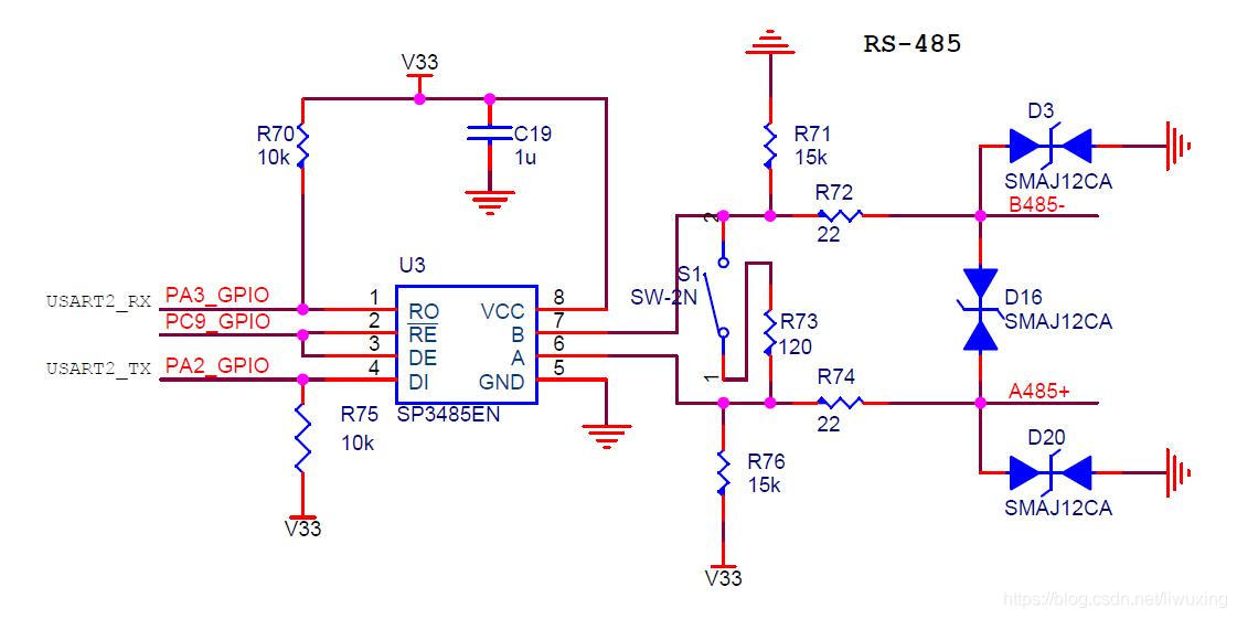
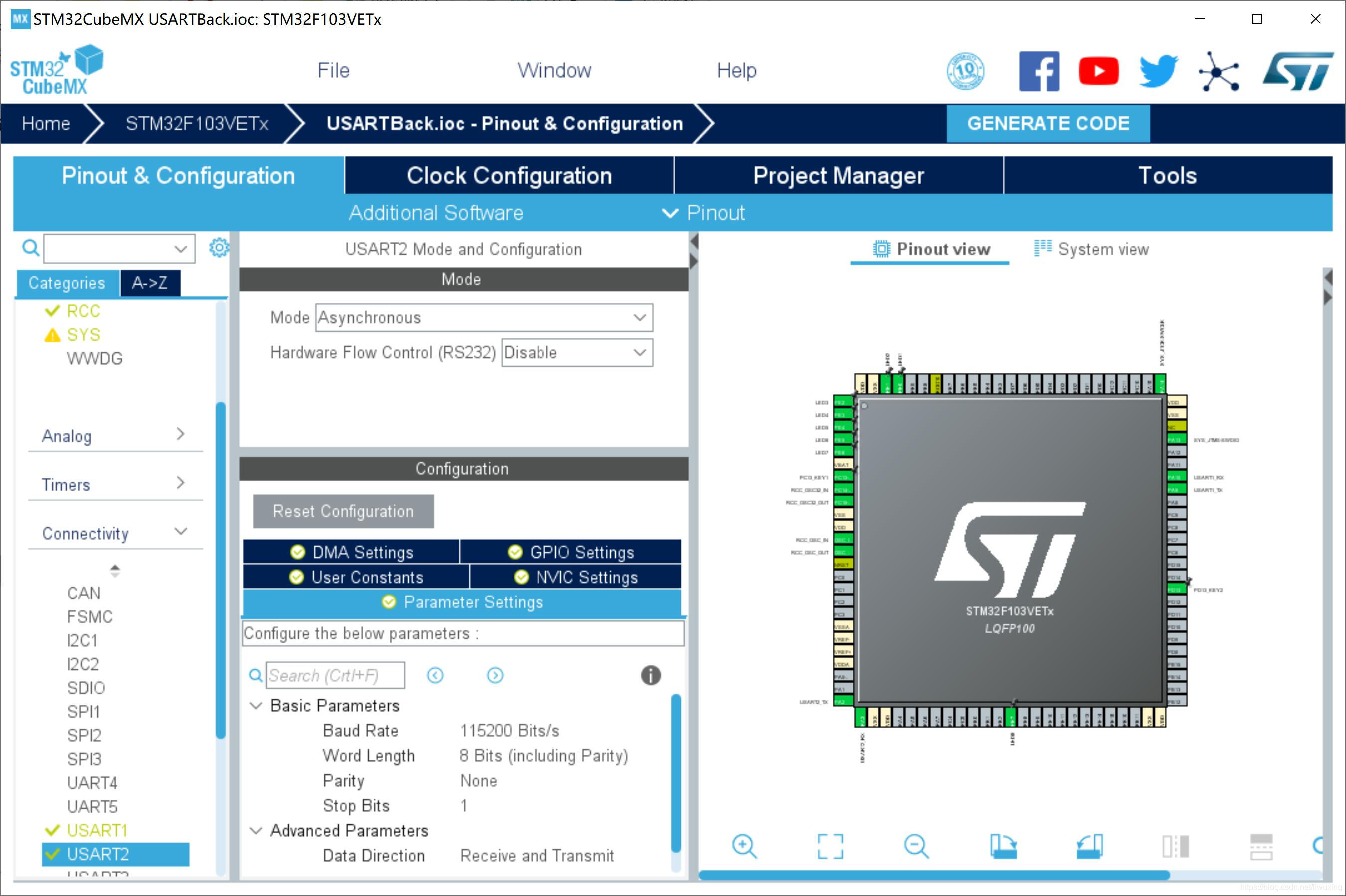
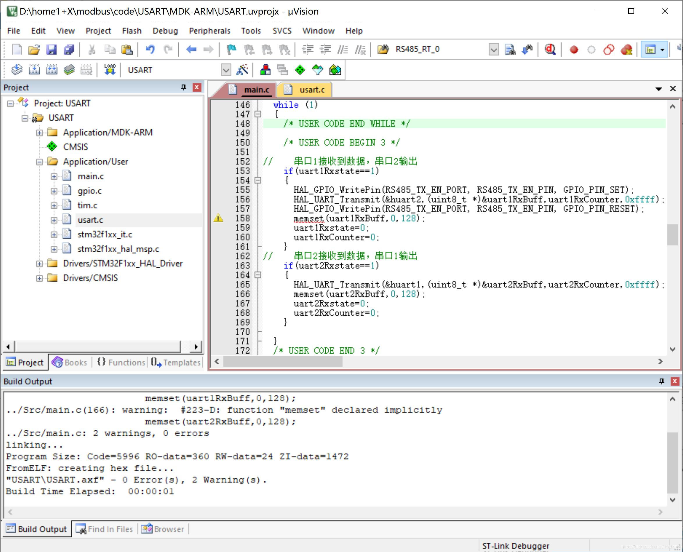
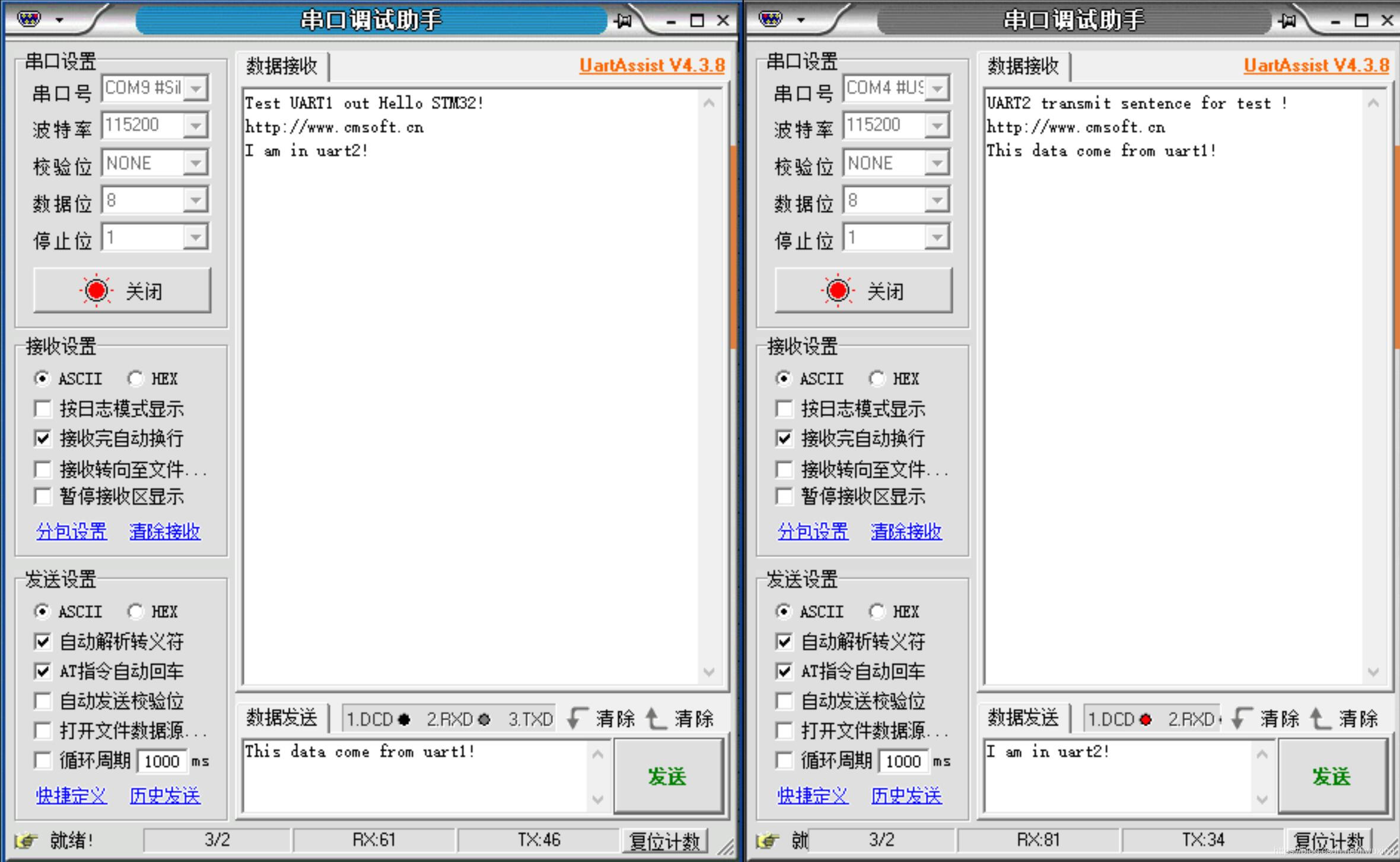
一、硬件电路 STM32F103EVT6基本电路;选择串口1、串口2;串口2通过485接口输出,控制端是PC9端口,PC9=1时接收,0时发送。 二、CubeMX完成配置,生成工程 配置时钟、调试模式、IO、串口1、串口2参数、打开串口中断。 三、Keil添加代码,完成功能 /* USER CODE BEGIN PV */ //接收状态,完毕标志为1;处于接收状态则为0 uint8_t uart1Rxstate=0; //当前接收的字节总数 uint8_t uart1RxCounter=0; //接收缓冲 uint8_t uart1RxBuff[128]={0}; //uart2接收 //接收状态,完毕标志为1;处于接收状态则为0 uint8_t uart2Rxstate=0; //当前接收的字节总数 uint8_t uart2RxCounter=0; //接收缓冲 uint8_t uart2RxBuff[128]={0}; void USER_UART2_IRQHandler(void); /* USER CODE END PV */ /* Private function prototypes -----------------------------------------------*/ void SystemClock_Config(void); /* USER CODE BEGIN PFP */ /* USER CODE END PFP */ /* Private user code ---------------------------------------------------------*/ /* USER CODE BEGIN 0 */ int fputc(int ch,FILE *f) { HAL_UART_Transmit(&huart1,(uint8_t *)&ch,1,0xffff); return ch; } /* USER CODE END 0 */ /** * @brief The application entry point. * @retval int */ int main(void) { /* USER CODE BEGIN 1 */ /* USER CODE END 1 */ /* MCU Configuration--------------------------------------------------------*/ /* Reset of all peripherals, Initializes the Flash interface and the Systick. */ HAL_Init(); /* USER CODE BEGIN Init */ /* USER CODE END Init */ /* Configure the system clock */ SystemClock_Config(); /* USER CODE BEGIN SysInit */ /* USER CODE END SysInit */ /* Initialize all configured peripherals */ MX_GPIO_Init(); MX_TIM6_Init(); MX_USART1_UART_Init(); MX_USART2_UART_Init(); /* USER CODE BEGIN 2 */ //开串口中断 __HAL_UART_ENABLE_IT(&huart1,UART_IT_RXNE); __HAL_UART_ENABLE_IT(&huart2,UART_IT_RXNE); //串口2 485接收使能 HAL_GPIO_WritePin(RS485_TX_EN_PORT, RS485_TX_EN_PIN, GPIO_PIN_RESET); printf("Test UART1 out Hello STM32!"); char tr2[]="UART2 transmit sentence for test !"; HAL_Delay(500); HAL_GPIO_WritePin(RS485_TX_EN_PORT, RS485_TX_EN_PIN, GPIO_PIN_SET); HAL_UART_Transmit(&huart2,(uint8_t *)&tr2,sizeof(tr2),0xffff); HAL_GPIO_WritePin(RS485_TX_EN_PORT, RS485_TX_EN_PIN, GPIO_PIN_RESET); HAL_Delay(500); /* USER CODE END 2 */ /* Infinite loop */ /* USER CODE BEGIN WHILE */ while (1) { /* USER CODE END WHILE */ /* USER CODE BEGIN 3 */ // 串口1接收到数据,串口2输出 if(uart1Rxstate==1) { HAL_GPIO_WritePin(RS485_TX_EN_PORT, RS485_TX_EN_PIN, GPIO_PIN_SET); HAL_UART_Transmit(&huart2,(uint8_t *)&uart1RxBuff,uart1RxCounter,0xffff); HAL_GPIO_WritePin(RS485_TX_EN_PORT, RS485_TX_EN_PIN, GPIO_PIN_RESET); memset(uart1RxBuff,0,128); uart1Rxstate=0; uart1RxCounter=0; } // 串口2接收到数据,串口1输出 if(uart2Rxstate==1) { HAL_UART_Transmit(&huart1,(uint8_t *)&uart2RxBuff,uart2RxCounter,0xffff); memset(uart2RxBuff,0,128); uart2Rxstate=0; uart2RxCounter=0; } } /* USER CODE END 3 */ } 四、串口调试工具调试测试 利用串口调试工具调试。
一、硬件电路 STM32F103EVT6基本电路;选择串口1、串口2;串口2通过485接口输出,控制端是PC9端口,PC9=1时接收,0时发送。 二、CubeMX完成配置,生成工程 配置时钟、调试模式、IO、串口1、串口2参数、打开串口中断。 三、Keil添加代码,完成功能 /* USER CODE BEGIN PV */ //接收状态,完毕标志为1;处于接收状态则为0 uint8_t uart1Rxstate=0; //当前接收的字节总数 uint8_t uart1RxCounter=0; //接收缓冲 uint8_t uart1RxBuff[128]={0}; //uart2接收 //接收状态,完毕标志为1;处于接收状态则为0 uint8_t uart2Rxstate=0; //当前接收的字节总数 uint8_t uart2RxCounter=0; //接收缓冲 uint8_t uart2RxBuff[128]={0}; void USER_UART2_IRQHandler(void); /* USER CODE END PV */ /* Private function prototypes -----------------------------------------------*/ void SystemClock_Config(void); /* USER CODE BEGIN PFP */ /* USER CODE END PFP */ /* Private user code ---------------------------------------------------------*/ /* USER CODE BEGIN 0 */ int fputc(int ch,FILE *f) { HAL_UART_Transmit(&huart1,(uint8_t *)&ch,1,0xffff); return ch; } /* USER CODE END 0 */ /** * @brief The application entry point. * @retval int */ int main(void) { /* USER CODE BEGIN 1 */ /* USER CODE END 1 */ /* MCU Configuration--------------------------------------------------------*/ /* Reset of all peripherals, Initializes the Flash interface and the Systick. */ HAL_Init(); /* USER CODE BEGIN Init */ /* USER CODE END Init */ /* Configure the system clock */ SystemClock_Config(); /* USER CODE BEGIN SysInit */ /* USER CODE END SysInit */ /* Initialize all configured peripherals */ MX_GPIO_Init(); MX_TIM6_Init(); MX_USART1_UART_Init(); MX_USART2_UART_Init(); /* USER CODE BEGIN 2 */ //开串口中断 __HAL_UART_ENABLE_IT(&huart1,UART_IT_RXNE); __HAL_UART_ENABLE_IT(&huart2,UART_IT_RXNE); //串口2 485接收使能 HAL_GPIO_WritePin(RS485_TX_EN_PORT, RS485_TX_EN_PIN, GPIO_PIN_RESET); printf("Test UART1 out Hello STM32!"); char tr2[]="UART2 transmit sentence for test !"; HAL_Delay(500); HAL_GPIO_WritePin(RS485_TX_EN_PORT, RS485_TX_EN_PIN, GPIO_PIN_SET); HAL_UART_Transmit(&huart2,(uint8_t *)&tr2,sizeof(tr2),0xffff); HAL_GPIO_WritePin(RS485_TX_EN_PORT, RS485_TX_EN_PIN, GPIO_PIN_RESET); HAL_Delay(500); /* USER CODE END 2 */ /* Infinite loop */ /* USER CODE BEGIN WHILE */ while (1) { /* USER CODE END WHILE */ /* USER CODE BEGIN 3 */ // 串口1接收到数据,串口2输出 if(uart1Rxstate==1) { HAL_GPIO_WritePin(RS485_TX_EN_PORT, RS485_TX_EN_PIN, GPIO_PIN_SET); HAL_UART_Transmit(&huart2,(uint8_t *)&uart1RxBuff,uart1RxCounter,0xffff); HAL_GPIO_WritePin(RS485_TX_EN_PORT, RS485_TX_EN_PIN, GPIO_PIN_RESET); memset(uart1RxBuff,0,128); uart1Rxstate=0; uart1RxCounter=0; } // 串口2接收到数据,串口1输出 if(uart2Rxstate==1) { HAL_UART_Transmit(&huart1,(uint8_t *)&uart2RxBuff,uart2RxCounter,0xffff); memset(uart2RxBuff,0,128); uart2Rxstate=0; uart2RxCounter=0; } } /* USER CODE END 3 */ } 四、串口调试工具调试测试 利用串口调试工具调试。
举报
更多回帖


 举报
举报

