STM32 的 IO 口相比51而言要复杂得多,每个 IO 端口都有 7 个寄存器来控制。他们分别是:
2个32位配置寄存器,GPIOx_CRL、GPIOx_CRH
2个32位数据寄存器,GPIOx_IDR、GPIOx_ODR
1个32位置位/复位寄存器,GPIOx_BSRR
1个16位复位寄存器,GPIOx_BRR
1个32位锁存寄存器,GPIOx_LCKR
每个通用 IO(GPIO)端口的端口位,可由软件单独配置为以下8种模式:1、输入浮空,2、输入上拉,3、输入下拉,4、模拟输入,5、开漏输出,6、推挽输出,7、推挽式复用功能,8、开漏复用功能
每个 IO 口可以自由编程, 但 IO 口寄存器必须要按 32 位字被访问。
0x01、GPIO的寄存器
寄存器相关的介绍在文件RM0008-Reference manual 中
0x0001、GPIOx_CRL
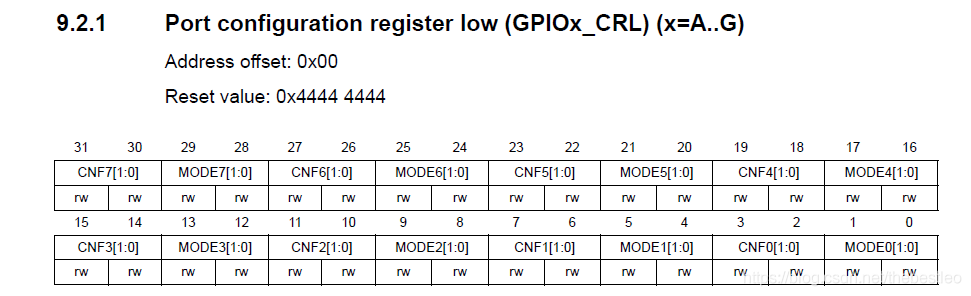
Bits 31:30、27:26、23:22、19:18、15:14、11:10、7:6、3:2
These bits are written by software to configure the corresponding I/O port.
这些为可以通过软件编写来控制相应的 I/O 口
CNFy[1:0]:Port x configuration bits (y = 0 。. 7) 端口配置位
输入模式下:(MODE[1:0] = 00)
00:Analog mode 模拟输入模式
01:Floating input (reset state) 浮空输入模式(复位后的状态)
10:Input with pull-up / pull-down 上拉/下拉输入模式
11:Reserved 保留
输出模式下:(MODE[1:0] 》 00)
00: General purpose output push-pull 通用推挽输出模式
01:General purpose output Open-drain 通用开漏输出模式
10:Alternate function output Push-pull 复用功能推挽输出模式
11:Alternate function output Open-drain 复用功能开漏输出模式
Bits 29:28、25:24、21:20、17:16、13:12、9:8、5:4、1:0
These bits are written by software to configure the corresponding I/O port.
这些为可以通过软件编写来控制相应的 I/O 口
MODEy[1:0]: Port x mode bits (y = 0 。. 7) 端口配置位
00: Input mode (reset state) 输入模式(复位后的状态)
01:Output mode, max speed 10 MHz 输出模式,最高速率10MHz
10:Output mode, max speed 2 MHz 输出模式,最高速率2MHz
11:Output mode, max speed 50 MHz 输出模式,最高速率50MHz
0x0002、GPIOx_CRH

Bits 31:30、27:26、23:22、19:18、15:14、11:10、7:6、3:2
These bits are written by software to configure the corresponding I/O port.
这些为可以通过软件编写来控制相应的 I/O 口
CNFy[1:0]:Port x configuration bits (y = 8 。. 15) 端口配置位
输入模式下:(MODE[1:0] = 00)
00:Analog mode 模拟输入模式
01:Floating input (reset state) 浮空输入模式(复位后的状态)
10:Input with pull-up / pull-down 上拉/下拉输入模式
11:Reserved 保留
输出模式下:(MODE[1:0] 》 00)
00: General purpose output push-pull 通用推挽输出模式
01:General purpose output Open-drain 通用开漏输出模式
10:Alternate function output Push-pull 复用功能推挽输出模式
11:Alternate function output Open-drain 复用功能开漏输出模式
Bits 29:28、25:24、21:20、17:16、13:12、9:8、5:4、1:0
These bits are written by software to configure the corresponding I/O port.
这些为可以通过软件编写来控制相应的 I/O 口
MODEy[1:0]: Port x mode bits (y = 8 。. 15) 端口配置位
00: Input mode (reset state) 输入模式(复位后的状态)
01:Output mode, max speed 10 MHz 输出模式,最高速率10MHz
10:Output mode, max speed 2 MHz 输出模式,最高速率2MHz
11:Output mode, max speed 50 MHz 输出模式,最高速率50MHz
0x0003、GPIOx_IDR
These bits are read only and can be accessed in Word mode only. They contain the input value of the corresponding I/O port.
GPIOx_IDR为输入状态寄存器,该寄存器为只读寄存器,并且只能以16 位的形式读出。
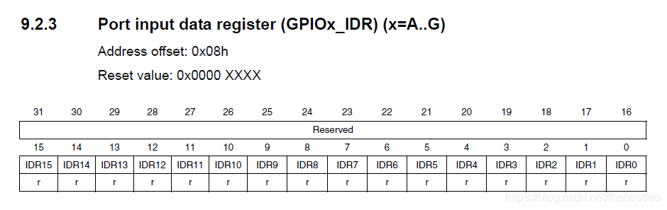
Bits 15:0 IDRy: Port input data (y= 0 。. 15) 读取的值对应 IO 口的状态
0x0004、GPIOx_ODR
These bits can be read and written by software and can be accessed in Word mode only.
GPIOx_ODR为输出状态寄存器,该寄存器可读可写,但只能以16 位的形式读写。
Note: For atomic bit set/reset, the ODR bits can be individually set and cleared by writing to the GPIOx_BSRR register (x = A 。. G)。
注意:ODR位可以通过设置GPIOx_BSRR寄存器来实现置位或者复位
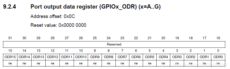
Bits 15:0 ODRy: Port output data (y= 0 。. 15)
0x0005、GPIOx_BSRR
对输出端口进行置位/复位的寄存器,可以用来设置 GPIO 端口的输出位是 0 还是 1。
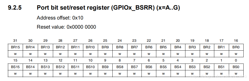
Bits 31:16 BRy:Port x Reset bit y (y = 0 。. 15)
These bits are write-only and can be accessed in Word mode only. 这些位只支持写操作,并且只能按16位写入。
0: No action on the corresponding ODRx bit 对输出端口不产生影响
1: Reset the corresponding ODRx bit 复位输出端口为0
Note: If both BSx and BRx are set, BSx has priority. 注意:如果同时设置了BSx和BRx,则BSx具有优先权。
Bits 15:0 BSy:Port x Set bit y (y = 0 。. 15)
These bits are write-only and can be accessed in Word mode only. 这些位只支持写操作,并且只能按16位写入。
0: No action on the corresponding ODRx bit 对输出端口不产生影响
1: Set the corresponding ODRx bit 置位输出端口为1
0x0006、GPIOx_BRR
输出端口复位寄存器,将输出端口复位为0
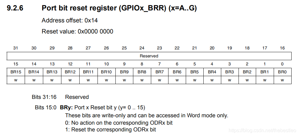
Bits 31:16 Reserved 保留
Bits 15:0 BRy: Port x Reset bit y (y = 0 。. 15)
These bits are write-only and can be accessed in Word mode only. 这些位只支持写操作,并且只能按16位写入。
0: No action on the corresponding ODRx bit 对输出端口不产生影响
1: Reset the corresponding ODRx bit 复位输出端口为0
0x0007、GPIOx_LCKR
该寄存器用来锁定端口配置,再下一次复位之前保持端口状态不被更改。
This register is used to lock the configuration of the port bits when a correct write sequence is applied to bit 16 (LCKK)。 The value of bits [15:0] is used to lock the configuration of the GPIO. During the write sequence, the value of LCKR[15:0] must not change. When the LOCK sequence has been applied on a port bit it is no longer possible to modify the value of the port bit until the next reset.
该寄存器在被写入正确的序列时,将锁定端口的配置。位0到15用于锁定GPIO配置。在序列写入时,LCKR寄存器不能被更改。当锁定序列被应用于1个端口时,该端口的状态无法被改变,直到下一次复位。
Each lock bit freezes the corresponding 4 bits of the control register (CRL, CRH)。 每个锁存位可以锁定控制寄存器的4位
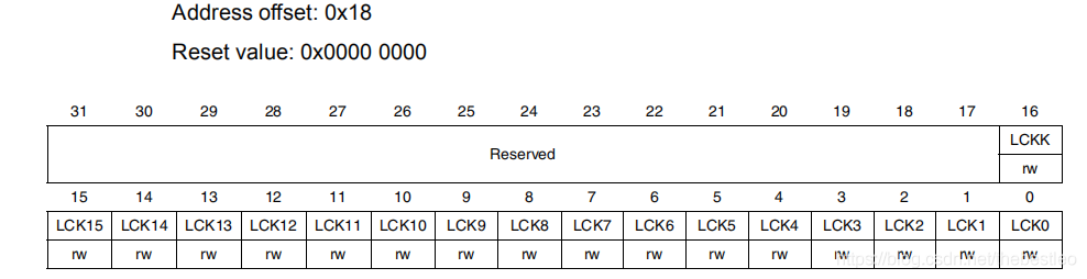
Bits 31:17 Reserved
Bit 16 LCKK[16]: Lock key
This bit can be read anytime. It can only be modified using the Lock Key Writing Sequence.
这个位可以随时读取。只能用Lock Key修改写入序列。
0: Port configuration lock key not active
端口配置锁定未激活
1: Port configuration lock key active. GPIOx_LCKR register is locked until the next reset.
端口配置锁定激活,GPIOx_LCKR被锁定,直到下一次复位
LOCK key writing sequence: Lock Key写入序列
Write 1
Write 0
Write 1
Read 0
Read 1 (this read is optional but confirms that the lock is active)
此读取是可选的,但需要确认锁定处于活动状态
Note: During the LOCK Key Writing sequence, the value of LCK[15:0] must not change.
注意:在锁定序列写入时,LCK的15到0位必须不能改变
Any error in the lock sequence will abort the lock. 锁定序列中的任何错误都将中止锁定。
Bits 15:0 LCKy: Port x Lock bit y (y = 0 。. 15)
These bits are read write but can only be written when the LCKK bit is 0.
这些位都可读写操作,但是只可以在LCKK位为0时执行写操作
0: Port configuration not locked 端口配置未锁定
1: Port configuration locked. 端口配置锁定
0x02、GPIO的相关库函数
0x0001、GPIO初始化函数
void GPIO_Init(GPIO_TypeDef* GPIOx, GPIO_InitTypeDef* GPIO_InitStruct)
函数功能:根据指定的参数初始化GPIOx外设。
参数1:GPIO_TypeDef* GPIOx —》 指定GPIO端口
参数2:GPIO_InitTypeDef* GPIO_InitStruct —》 指向包含指定GPIO外围设备配置信息的GPIO_InitTypeDef结构体的指针。
返回值:无
0x0002、读取GPIO函数
uint8_t GPIO_ReadInputDataBit(GPIO_TypeDef* GPIOx, uint16_t GPIO_Pin)
函数功能:读取指定的输入端口引脚。
参数1:GPIO_TypeDef* GPIOx —》 指定GPIO端口
参数2:uint16_t GPIO_Pin —》 指定要读取的端口位,GPIO_Pin_x,其中x可以是(0..15)
返回值:bitstatus,输入端口引脚值。
0x0003、写入GPIO函数
void GPIO_Write(GPIO_TypeDef* GPIOx, uint16_t PortVal)
函数功能:写指定的GPIO端口。
参数1:GPIO_TypeDef* GPIOx —》 指定GPIO端口
参数2:uint16_t PortVal —》 指定要写入端口输出数据寄存器的值。
返回值:无
0x0004、置位函数
void GPIO_SetBits(GPIO_TypeDef* GPIOx, uint16_t GPIO_Pin)
函数功能:置位选定的数据端口位。
参数1:GPIO_TypeDef* GPIOx —》 指定GPIO端口
参数2:uint16_t GPIO_Pin —》 指定要写入的端口位,GPIO_Pin_x,其中x可以是(0..15)
返回值:无
0x0005、复位函数
void GPIO_ResetBits(GPIO_TypeDef* GPIOx, uint16_t GPIO_Pin)
函数功能:复位选定的数据端口位。
参数1:GPIO_TypeDef* GPIOx —》 指定GPIO端口
参数2:uint16_t GPIO_Pin —》 指定要写入的端口位,GPIO_Pin_x,其中x可以是(0..15)
返回值:无
0x03、自行编写的GPIO初始化函数
void LED_Init(void)
{
GPIO_InitTypeDef GPIO_InitStructure; // 定义GPIO_InitTypeDef结构体
RCC_APB2PeriphClockCmd(RCC_APB2Periph_GPIOC, ENABLE); // 初始化GPIOC的时钟
GPIO_InitStructure.GPIO_Pin = GPIO_Pin_10; // 选择GPIO_Pin_10
GPIO_InitStructure.GPIO_Mode = GPIO_Mode_Out_PP; // 推挽输出模式
GPIO_InitStructure.GPIO_Speed = GPIO_Speed_50MHz; // 输出速率50MHz
GPIO_Init(GPIOC,&GPIO_InitStructure); // 初始化GPIOC
GPIO_SetBits(GPIOC,GPIO_Pin_10); // 初始化GPIO_Pin_10为低电平(熄灭LED)
}
STM32 的 IO 口相比51而言要复杂得多,每个 IO 端口都有 7 个寄存器来控制。他们分别是:
2个32位配置寄存器,GPIOx_CRL、GPIOx_CRH
2个32位数据寄存器,GPIOx_IDR、GPIOx_ODR
1个32位置位/复位寄存器,GPIOx_BSRR
1个16位复位寄存器,GPIOx_BRR
1个32位锁存寄存器,GPIOx_LCKR
每个通用 IO(GPIO)端口的端口位,可由软件单独配置为以下8种模式:1、输入浮空,2、输入上拉,3、输入下拉,4、模拟输入,5、开漏输出,6、推挽输出,7、推挽式复用功能,8、开漏复用功能
每个 IO 口可以自由编程, 但 IO 口寄存器必须要按 32 位字被访问。
0x01、GPIO的寄存器
寄存器相关的介绍在文件RM0008-Reference manual 中
0x0001、GPIOx_CRL
Bits 31:30、27:26、23:22、19:18、15:14、11:10、7:6、3:2
These bits are written by software to configure the corresponding I/O port.
这些为可以通过软件编写来控制相应的 I/O 口
CNFy[1:0]:Port x configuration bits (y = 0 。. 7) 端口配置位
输入模式下:(MODE[1:0] = 00)
00:Analog mode 模拟输入模式
01:Floating input (reset state) 浮空输入模式(复位后的状态)
10:Input with pull-up / pull-down 上拉/下拉输入模式
11:Reserved 保留
输出模式下:(MODE[1:0] 》 00)
00: General purpose output push-pull 通用推挽输出模式
01:General purpose output Open-drain 通用开漏输出模式
10:Alternate function output Push-pull 复用功能推挽输出模式
11:Alternate function output Open-drain 复用功能开漏输出模式
Bits 29:28、25:24、21:20、17:16、13:12、9:8、5:4、1:0
These bits are written by software to configure the corresponding I/O port.
这些为可以通过软件编写来控制相应的 I/O 口
MODEy[1:0]: Port x mode bits (y = 0 。. 7) 端口配置位
00: Input mode (reset state) 输入模式(复位后的状态)
01:Output mode, max speed 10 MHz 输出模式,最高速率10MHz
10:Output mode, max speed 2 MHz 输出模式,最高速率2MHz
11:Output mode, max speed 50 MHz 输出模式,最高速率50MHz
0x0002、GPIOx_CRH
Bits 31:30、27:26、23:22、19:18、15:14、11:10、7:6、3:2
These bits are written by software to configure the corresponding I/O port.
这些为可以通过软件编写来控制相应的 I/O 口
CNFy[1:0]:Port x configuration bits (y = 8 。. 15) 端口配置位
输入模式下:(MODE[1:0] = 00)
00:Analog mode 模拟输入模式
01:Floating input (reset state) 浮空输入模式(复位后的状态)
10:Input with pull-up / pull-down 上拉/下拉输入模式
11:Reserved 保留
输出模式下:(MODE[1:0] 》 00)
00: General purpose output push-pull 通用推挽输出模式
01:General purpose output Open-drain 通用开漏输出模式
10:Alternate function output Push-pull 复用功能推挽输出模式
11:Alternate function output Open-drain 复用功能开漏输出模式
Bits 29:28、25:24、21:20、17:16、13:12、9:8、5:4、1:0
These bits are written by software to configure the corresponding I/O port.
这些为可以通过软件编写来控制相应的 I/O 口
MODEy[1:0]: Port x mode bits (y = 8 。. 15) 端口配置位
00: Input mode (reset state) 输入模式(复位后的状态)
01:Output mode, max speed 10 MHz 输出模式,最高速率10MHz
10:Output mode, max speed 2 MHz 输出模式,最高速率2MHz
11:Output mode, max speed 50 MHz 输出模式,最高速率50MHz
0x0003、GPIOx_IDR
These bits are read only and can be accessed in Word mode only. They contain the input value of the corresponding I/O port.
GPIOx_IDR为输入状态寄存器,该寄存器为只读寄存器,并且只能以16 位的形式读出。
Bits 15:0 IDRy: Port input data (y= 0 。. 15) 读取的值对应 IO 口的状态
0x0004、GPIOx_ODR
These bits can be read and written by software and can be accessed in Word mode only.
GPIOx_ODR为输出状态寄存器,该寄存器可读可写,但只能以16 位的形式读写。
Note: For atomic bit set/reset, the ODR bits can be individually set and cleared by writing to the GPIOx_BSRR register (x = A 。. G)。
注意:ODR位可以通过设置GPIOx_BSRR寄存器来实现置位或者复位
Bits 15:0 ODRy: Port output data (y= 0 。. 15)
0x0005、GPIOx_BSRR
对输出端口进行置位/复位的寄存器,可以用来设置 GPIO 端口的输出位是 0 还是 1。
Bits 31:16 BRy:Port x Reset bit y (y = 0 。. 15)
These bits are write-only and can be accessed in Word mode only. 这些位只支持写操作,并且只能按16位写入。
0: No action on the corresponding ODRx bit 对输出端口不产生影响
1: Reset the corresponding ODRx bit 复位输出端口为0
Note: If both BSx and BRx are set, BSx has priority. 注意:如果同时设置了BSx和BRx,则BSx具有优先权。
Bits 15:0 BSy:Port x Set bit y (y = 0 。. 15)
These bits are write-only and can be accessed in Word mode only. 这些位只支持写操作,并且只能按16位写入。
0: No action on the corresponding ODRx bit 对输出端口不产生影响
1: Set the corresponding ODRx bit 置位输出端口为1
0x0006、GPIOx_BRR
输出端口复位寄存器,将输出端口复位为0
Bits 31:16 Reserved 保留
Bits 15:0 BRy: Port x Reset bit y (y = 0 。. 15)
These bits are write-only and can be accessed in Word mode only. 这些位只支持写操作,并且只能按16位写入。
0: No action on the corresponding ODRx bit 对输出端口不产生影响
1: Reset the corresponding ODRx bit 复位输出端口为0
0x0007、GPIOx_LCKR
该寄存器用来锁定端口配置,再下一次复位之前保持端口状态不被更改。
This register is used to lock the configuration of the port bits when a correct write sequence is applied to bit 16 (LCKK)。 The value of bits [15:0] is used to lock the configuration of the GPIO. During the write sequence, the value of LCKR[15:0] must not change. When the LOCK sequence has been applied on a port bit it is no longer possible to modify the value of the port bit until the next reset.
该寄存器在被写入正确的序列时,将锁定端口的配置。位0到15用于锁定GPIO配置。在序列写入时,LCKR寄存器不能被更改。当锁定序列被应用于1个端口时,该端口的状态无法被改变,直到下一次复位。
Each lock bit freezes the corresponding 4 bits of the control register (CRL, CRH)。 每个锁存位可以锁定控制寄存器的4位
Bits 31:17 Reserved
Bit 16 LCKK[16]: Lock key
This bit can be read anytime. It can only be modified using the Lock Key Writing Sequence.
这个位可以随时读取。只能用Lock Key修改写入序列。
0: Port configuration lock key not active
端口配置锁定未激活
1: Port configuration lock key active. GPIOx_LCKR register is locked until the next reset.
端口配置锁定激活,GPIOx_LCKR被锁定,直到下一次复位
LOCK key writing sequence: Lock Key写入序列
Write 1
Write 0
Write 1
Read 0
Read 1 (this read is optional but confirms that the lock is active)
此读取是可选的,但需要确认锁定处于活动状态
Note: During the LOCK Key Writing sequence, the value of LCK[15:0] must not change.
注意:在锁定序列写入时,LCK的15到0位必须不能改变
Any error in the lock sequence will abort the lock. 锁定序列中的任何错误都将中止锁定。
Bits 15:0 LCKy: Port x Lock bit y (y = 0 。. 15)
These bits are read write but can only be written when the LCKK bit is 0.
这些位都可读写操作,但是只可以在LCKK位为0时执行写操作
0: Port configuration not locked 端口配置未锁定
1: Port configuration locked. 端口配置锁定
0x02、GPIO的相关库函数
0x0001、GPIO初始化函数
void GPIO_Init(GPIO_TypeDef* GPIOx, GPIO_InitTypeDef* GPIO_InitStruct)
函数功能:根据指定的参数初始化GPIOx外设。
参数1:GPIO_TypeDef* GPIOx —》 指定GPIO端口
参数2:GPIO_InitTypeDef* GPIO_InitStruct —》 指向包含指定GPIO外围设备配置信息的GPIO_InitTypeDef结构体的指针。
返回值:无
0x0002、读取GPIO函数
uint8_t GPIO_ReadInputDataBit(GPIO_TypeDef* GPIOx, uint16_t GPIO_Pin)
函数功能:读取指定的输入端口引脚。
参数1:GPIO_TypeDef* GPIOx —》 指定GPIO端口
参数2:uint16_t GPIO_Pin —》 指定要读取的端口位,GPIO_Pin_x,其中x可以是(0..15)
返回值:bitstatus,输入端口引脚值。
0x0003、写入GPIO函数
void GPIO_Write(GPIO_TypeDef* GPIOx, uint16_t PortVal)
函数功能:写指定的GPIO端口。
参数1:GPIO_TypeDef* GPIOx —》 指定GPIO端口
参数2:uint16_t PortVal —》 指定要写入端口输出数据寄存器的值。
返回值:无
0x0004、置位函数
void GPIO_SetBits(GPIO_TypeDef* GPIOx, uint16_t GPIO_Pin)
函数功能:置位选定的数据端口位。
参数1:GPIO_TypeDef* GPIOx —》 指定GPIO端口
参数2:uint16_t GPIO_Pin —》 指定要写入的端口位,GPIO_Pin_x,其中x可以是(0..15)
返回值:无
0x0005、复位函数
void GPIO_ResetBits(GPIO_TypeDef* GPIOx, uint16_t GPIO_Pin)
函数功能:复位选定的数据端口位。
参数1:GPIO_TypeDef* GPIOx —》 指定GPIO端口
参数2:uint16_t GPIO_Pin —》 指定要写入的端口位,GPIO_Pin_x,其中x可以是(0..15)
返回值:无
0x03、自行编写的GPIO初始化函数
void LED_Init(void)
{
GPIO_InitTypeDef GPIO_InitStructure; // 定义GPIO_InitTypeDef结构体
RCC_APB2PeriphClockCmd(RCC_APB2Periph_GPIOC, ENABLE); // 初始化GPIOC的时钟
GPIO_InitStructure.GPIO_Pin = GPIO_Pin_10; // 选择GPIO_Pin_10
GPIO_InitStructure.GPIO_Mode = GPIO_Mode_Out_PP; // 推挽输出模式
GPIO_InitStructure.GPIO_Speed = GPIO_Speed_50MHz; // 输出速率50MHz
GPIO_Init(GPIOC,&GPIO_InitStructure); // 初始化GPIOC
GPIO_SetBits(GPIOC,GPIO_Pin_10); // 初始化GPIO_Pin_10为低电平(熄灭LED)
}

 举报
举报


