我确实找到了一些可以做的工作:HTTPS/2/256/MAX5033-1045 28PDF 76VIN 7VUA,70UA静态10UA关机3.50HTTPS://www. Mous.com/DS/2/256/Max 1562-257927.PDF 60Vin 5VUT 65%效率在5毫安48 VIN $2.50HTTP://www. Ti.COM/LIT/DS/Simulk/LM5165-Q1.PDF 6VIN,5VUT,205 UA有源,5UA关断,75%的效率在5毫安3.25美元,能够获得模拟小于1毫安从60V轨道抽出5V 5mA输出通过使用15mH电感器和2 kHz PWM与12USEC占空比。只有50%的效率。我还必须提供一些读取输出电压来调节PWM的方法。也许最好的总效率是在突发中运行调节器来充电一个电容器,它可以在样品之间的睡眠模式下为电路供电。这个BMS将被用于12V,12 AH的SLA电池,所以1Ma CON。在1000小时或超过一个月内,抽签将消耗10%的电荷。这可能类似于自我放逐。谢谢。
以上来自于百度翻译
以下为原文
I did find some that might do the job:
https://www.mouser.com/ds/2/256/MAX5033-104528.pdf 76Vin 5Vout 270uA quiescent 10uA shutdown $3.50
https://www.mouser.com/ds/2/256/MAX15062-257927.pdf 60Vin 5Vout 65% efficiency at 5 mA out 48Vin $2.50
http://www.ti.com/lit/ds/symlink/lm5165-q1.pdf 65Vin, 5Vout, 205 uA active, 5uA shutdown, 75% efficiency at 5 mA out $3.25
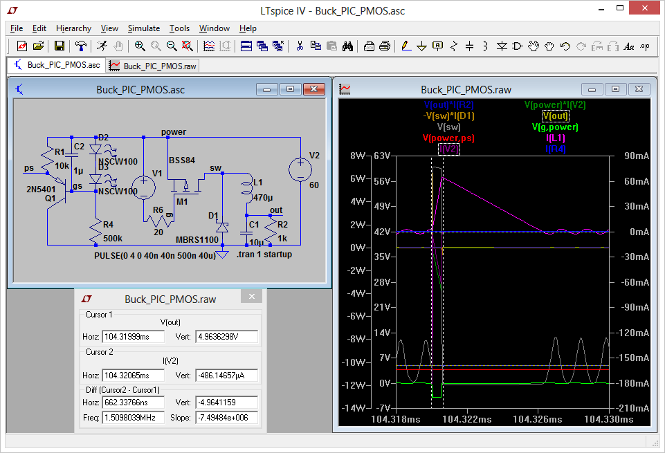
I was able to get a simulation with less than 1 mA draw from the 60V rail for 5V 5mA output by using a 15mH inductor and 2 kHz PWM with 12uSec duty cycle. Only 50% efficiency. I'd also have to provide some means of reading the output voltage to adjust the PWM.
Perhaps best overall efficiency would be to run the regulator in bursts to charge a capacitor that can power the circuit in sleep mode between samples.
This BMS will be used on 12V, 12 A-h SLA batteries, so a 1mA constant draw would drain 10% of charge in 1000 hours, or over a month. That's probably similar to self-discharge.
Thanks.
我确实找到了一些可以做的工作:HTTPS/2/256/MAX5033-1045 28PDF 76VIN 7VUA,70UA静态10UA关机3.50HTTPS://www. Mous.com/DS/2/256/Max 1562-257927.PDF 60Vin 5VUT 65%效率在5毫安48 VIN $2.50HTTP://www. Ti.COM/LIT/DS/Simulk/LM5165-Q1.PDF 6VIN,5VUT,205 UA有源,5UA关断,75%的效率在5毫安3.25美元,能够获得模拟小于1毫安从60V轨道抽出5V 5mA输出通过使用15mH电感器和2 kHz PWM与12USEC占空比。只有50%的效率。我还必须提供一些读取输出电压来调节PWM的方法。也许最好的总效率是在突发中运行调节器来充电一个电容器,它可以在样品之间的睡眠模式下为电路供电。这个BMS将被用于12V,12 AH的SLA电池,所以1Ma CON。在1000小时或超过一个月内,抽签将消耗10%的电荷。这可能类似于自我放逐。谢谢。
以上来自于百度翻译
以下为原文
I did find some that might do the job:
https://www.mouser.com/ds/2/256/MAX5033-104528.pdf 76Vin 5Vout 270uA quiescent 10uA shutdown $3.50
https://www.mouser.com/ds/2/256/MAX15062-257927.pdf 60Vin 5Vout 65% efficiency at 5 mA out 48Vin $2.50
http://www.ti.com/lit/ds/symlink/lm5165-q1.pdf 65Vin, 5Vout, 205 uA active, 5uA shutdown, 75% efficiency at 5 mA out $3.25
I was able to get a simulation with less than 1 mA draw from the 60V rail for 5V 5mA output by using a 15mH inductor and 2 kHz PWM with 12uSec duty cycle. Only 50% efficiency. I'd also have to provide some means of reading the output voltage to adjust the PWM.
Perhaps best overall efficiency would be to run the regulator in bursts to charge a capacitor that can power the circuit in sleep mode between samples.
This BMS will be used on 12V, 12 A-h SLA batteries, so a 1mA constant draw would drain 10% of charge in 1000 hours, or over a month. That's probably similar to self-discharge.
Thanks.

 举报
举报