想做一个简单的 微电容位移传感器 采用AD7150 来获得电容值
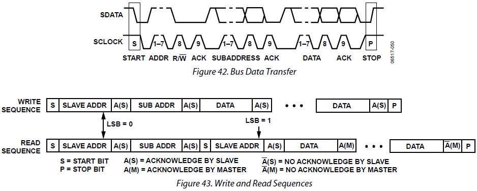
AD7150 是I2C传送数据,因为想做的简单,就用MSP430G2553
单片机做主控,模拟I2C
通信方式,来获取输入
程式语言部分该如何编码?
底下是我参考open source
msp430g2xx3_uscib0_i2c_12.c
进行修改
但不了解各个状态要如何设定 (寄存器位址等)?
请各位大大协助
#include
#include "msp430g2553.h"
#define NUM_BYTES_TX 1 // How many bytes?
#define NUM_BYTES_RX 1
int RXByteCtr, RPT_Flag = 0; // enables repeated start when 1
volatile unsigned char RxBuffer[128]; // Allocate 128 byte of RAM
unsigned char *PTxData; // Pointer to TX data
unsigned char *PRxData; // Pointer to RX data
unsigned char TXByteCtr, RX = 0;
unsigned char MSData = 0x55;
unsigned int RxWord;
unsigned int RxByteCtr;
unsigned char i;
float pFdata;
float chRange;
void Setup_TX(void);
void Setup_RX(void);
void Transmit(void);
void Receive(void);
float AD7150_Cap(void);
void main(void)
{
WDTCTL = WDTPW + WDTHOLD; // Stop WDT
P1SEL |= BIT6 + BIT7; // Assign I2C pins to USCI_B0
P1SEL2|= BIT6 + BIT7; // Assign I2C pins to USCI_B0
while(1){
//Transmit process
Setup_TX();
RPT_Flag = 1;
Transmit();
while (UCB0CTL1 & UCTXSTP); // Ensure stop condition got sent
//Receive process
Setup_RX();
Receive();
while (UCB0CTL1 & UCTXSTP); // Ensure stop condition got sent
}
}
//-------------------------------------------------------------------------------
// The USCI_B0 data ISR is used to move received data from the I2C slave
// to the MSP430 memory. It is structured such that it can be used to receive
// any 2+ number of bytes by pre-loading RXByteCtr with the byte count.
//-------------------------------------------------------------------------------
#pragma vector = USCIAB0TX_VECTOR
__interrupt void USCIAB0TX_ISR(void)
{
if(RX == 1){ // Master Recieve?
RXByteCtr--; // Decrement RX byte counter
if (RXByteCtr)
{
*PRxData++ = UCB0RXBUF; // Move RX data to address PRxData
}
else
{
if(RPT_Flag == 0)
UCB0CTL1 |= UCTXSTP; // No Repeated Start: stop condition
if(RPT_Flag == 1){ // if Repeated Start: do nothing
RPT_Flag = 0;
}
*PRxData = UCB0RXBUF; // Move final RX data to PRxData
__bic_SR_register_on_exit(CPUOFF); // Exit LPM0
}}
else{ // Master Transmit
if (TXByteCtr) // Check TX byte counter
{
UCB0TXBUF = MSData++; // Load TX buffer
TXByteCtr--; // Decrement TX byte counter
}
else
{
if(RPT_Flag == 1){
RPT_Flag = 0;
PTxData = &MSData; // TX array start address
TXByteCtr = NUM_BYTES_TX; // Load TX byte counter
__bic_SR_register_on_exit(CPUOFF);
}
else{
UCB0CTL1 |= UCTXSTP; // I2C stop condition
IFG2 &= ~UCB0TXIFG; // Clear USCI_B0 TX int flag
__bic_SR_register_on_exit(CPUOFF); // Exit LPM0
}
}
}
}
void Setup_TX(void){
_DINT();
RX = 0;
IE2 &= ~UCB0RXIE;
while (UCB0CTL1 & UCTXSTP); // Ensure stop condition got sent// Disable RX interrupt
UCB0CTL1 |= UCSWRST; // Enable SW reset
UCB0CTL0 = UCMST + UCMODE_3 + UCSYNC; // I2C Master, synchronous mode
UCB0CTL1 = UCSSEL_2 + UCSWRST; // Use SMCLK, keep SW reset
UCB0BR0 = 12; // fSCL = SMCLK/12 = ~100kHz
UCB0BR1 = 0;
UCB0I2CSA = 0x48; // Slave Address is 048h
UCB0CTL1 &= ~UCSWRST; // Clear SW reset, resume operation
IE2 |= UCB0TXIE; // Enable TX interrupt
}
void Setup_RX(void){
_DINT();
RX = 1;
IE2 &= ~UCB0TXIE;
UCB0CTL1 |= UCSWRST; // Enable SW reset
UCB0CTL0 = UCMST + UCMODE_3 + UCSYNC; // I2C Master, synchronous mode
UCB0CTL1 = UCSSEL_2 + UCSWRST; // Use SMCLK, keep SW reset
UCB0BR0 = 12; // fSCL = SMCLK/12 = ~100kHz
UCB0BR1 = 0;
UCB0I2CSA = 0x48; // Slave Address is 048h
UCB0CTL1 &= ~UCSWRST; // Clear SW reset, resume operation
IE2 |= UCB0RXIE; // Enable RX interrupt
}
void Transmit(void){
PTxData = &MSData; // TX array start address
TXByteCtr = NUM_BYTES_TX; // Load TX byte counter
while (UCB0CTL1 & UCTXSTP); // Ensure stop condition got sent
UCB0CTL1 |= UCTR + UCTXSTT; // I2C TX, start condition
__bis_SR_register(CPUOFF + GIE); // Enter LPM0 w/ interrupts
}
void Receive(void){
PRxData = (unsigned char *)RxBuffer; // Start of RX buffer
RXByteCtr = NUM_BYTES_RX-1; // Load RX byte counter
while (UCB0CTL1 & UCTXSTP); // Ensure stop condition got sent
UCB0CTL1 |= UCTXSTT; // I2C start condition
__bis_SR_register(CPUOFF + GIE); // Enter LPM0 w/ interrupts
}
float AD7150_Cap(void)
{
if(RxByteCtr < 0x3000)
{
RxByteCtr = 0x3000;
}
else if ( RxByteCtr >0XD000)
{
RxByteCtr = 0XD000;
}
pFdata =(((RxByteCtr)-0x3000)*1)/0x9FF0;
return pFdata;
}
最後是根據data sheet 所提供公式進行修改


 举报
举报


 举报
举报

